For the circuits shown in figures 1 and 2:- What is the function of output? 2. Find the max. and min. VOL value? Determine the static power (avg.)? 1. Design equivalent logic circuit by CMOC logic cir VDD= 10 V, VT 1 V. VTL-1V. (W/L) = (5/2) 40k, KL=10 u A/V2 and KO= 40μ A/V^2?
For the circuits shown in figures 1 and 2:- What is the function of output? 2. Find the max. and min. VOL value? Determine the static power (avg.)? 1. Design equivalent logic circuit by CMOC logic cir VDD= 10 V, VT 1 V. VTL-1V. (W/L) = (5/2) 40k, KL=10 u A/V2 and KO= 40μ A/V^2?

Chapter22: Sequence Control
Section: Chapter Questions
Problem 6SQ: Draw a symbol for a solid-state logic element AND.

Related questions
Question
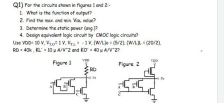
Transcribed Image Text:Q1) For the circuits shown in figures 1 and 2:
1. What is the function of output?
2. Find the max. and min. Vol. value?
3. Determine the static power (avg.)?
4. Design equivalent logic circuit by CMOC logic circuits?
Use VDD= 10 V. Vr.o=1V. Vru-1V. (W/L)o= (5/2), (W/L)L (20/2),
RD = 40k, KL = 10P A/V^2 and KO = 40pA/V`2?
Figure 1
5
VDD
RD
Figure 2
बदना
दे
Expert Solution
This question has been solved!
Explore an expertly crafted, step-by-step solution for a thorough understanding of key concepts.

Step by step
Solved in 3 steps with 3 images

Knowledge Booster


Learn more about
Need a deep-dive on the concept behind this application? Look no further. Learn more about this topic, electrical-engineering and related others by exploring similar questions and additional content below.Recommended textbooks for you