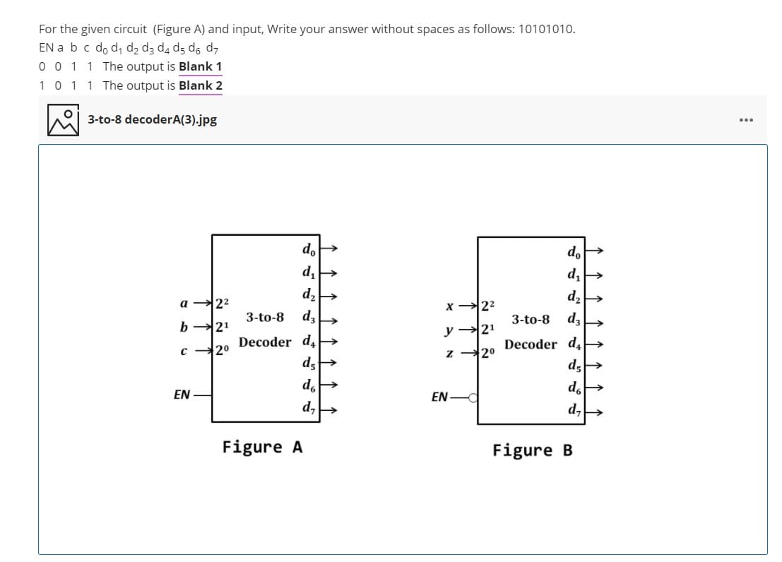
For the given circuit (Figure A) and input, Write your answer without spaces as follows: 10101010. EN a bc do d, d2 d3 d4 d5 dó d7 0 0 1 1 The output is Blank 1 101 1 The output is Blank 2 3-to-8 decoderA(3).jpg ... do do a 22 x 22 3-to-8 d, 3-to-8 dz b 21 y →21 Decoder d,> Decoder d, 20 c - 2° EN EN - d, Figure A Figure B 1 ↑ ↑ ↑ 个 ↑↑ ↑↑1


Q: Question [1]:. A combinational circuit is divided into two sub-circuits N1 and N2 as shown. The…
A: Answer: 4) Boolean expressions for D,E,F in simplified POS form are as follows: D =…
Q: 1. For truth tables as shown in below, use different circuits to implement this fun A B C D F 0 1 .0…
A: For 8x1 MUX, number of select lines = 3. Let these 3 select lines be ABC For 4x1MUX, number of…
Q: Confirm circuit in Figure 3 is equivalent to circuit in Figure 1 by simulating the circuit and…
A: Both figures contains, Input variables= {A, B, C, D} Intermediate variables= {E, F, G} Output…
Q: Evaluate the difference X = Y - Z, where Y = 10001110 and Z = 11110000.
A: As per our guidlines we are supposed to answer only one question Subtraction of two binary number…
Q: The state table of a sequential circuit is given as follow: Current state Q1 Q2 Next state Q1*Q2*…
A: - As provided in the table the current state value after the value of x as 0 and 1 the values…
Q: Q5. truth table, using PLA Implement the combinational circuit having the shown Inputs Outputs ABC…
A:
Q: For the below circuit, find Req across the source in KQ. 3 kng 5 kng 4 kfl 3 mA 10 kΩ 7 kn3 Select…
A: Correct answer - option (b)
Q: Is the n the following circuit? EN DO 2X1 MUX DO 01 1-40-2 Decoder D1 B EN DO 2X1 MUX C 01 so B
A: Let's consider a scenario A=0 Then D0 is high. Thus the upper MUX will be selected. Now when B=0,…
Q: Consider the following Mealy sequential circuit. Present Next State Output Z State X = 0 X = 1 X=0 X…
A:
Q: For the circuit shown below, determine the Boolean functions at point X and Y as well as the output…
A: Please check the step 2 for solution
Q: Part 1 1. Determine the Boolean Function of the C, D, E, F, G nodes for the circuit given in Figure…
A: Answer is given below .
Q: Given the below Function: F(x, y, z) = (x + y). (y + z) + xyz a- Draw the combinational circuit that…
A: Solution :
Q: Find the Boolean expression of the following circuit, draw the circuit on EWB and simulate it to…
A:
Q: Based on the given circuit, what are the values of J and K, when A=1, B=1, C=1? 4 to 1 MUX C' J…
A: Need to find the value of J and K, for the given circuit : When J gets input from 4:1 MUX and K…
Q: For the following Moore machine, q/1) 9o/0 1 1 q:/0) 1 if the input string is 1010111, what would be…
A: Here in this question we have given a moore machine with some input string and we have asked to…
Q: Given the below Function: F(X, y, z) = (x + y). (y + z) + xyz a- Draw the combinational circuit that…
A: answer is given below:
Q: 3. Derive the Boolean expression of the output S and C as shown in the following circuit: (Show your…
A: Truth Table of 3 to 8 Decoder:
Q: Implement the following truth table directly (without any minimization) using a PLA. Properly label…
A: Given, Truth Table: W X Y Z A B C 0 0 0 0 1 0 1 0 0 0 1 1 0 0 0 0 1 0 0 1 1 0 0 1 1 0 0 0…
Q: In designing a circuit for the counter that detects two or more consecutive 1's in a string of input…
A:
Q: Consider the circuit as shown. If the state of (S1, SO) chänges in the sequence (0,0)-(1,1)…
A: Start by naming the AND gates A,B,C,D and OR gate as O
Q: Q5. Find the simplified expressons for Tl & Il and draw their logic circuits using Logisim. 0 0 0 0…
A:
Q: Q3. A sequential circuit has an input (X) and an output (Z). The output is the same as the input was…
A:
Q: The state diagram of a Moore machine is shown below. This machine has one input (a), if we design…
A:
Q: Implement the digital circuit shown in figure below using VHDL. X 10 2:1 MUX → f y Q D Cik
A: A device, which is acting like a building block for digital circuits, called logical circuit. It…
Q: Design a combinational logic circuit that converts a 4-bit binary number into its corresponding 2's…
A: Answer: 2's complement of a number will be first we need to convert o's of the given binary…
Q: Design a circuit with a 4-bit BCD input A, B, C, D that produces an output W, X, Y, Z that is equal…
A: Detailed explanation is given below
Q: For the circuit in the figure, indicate the value of Q at time T3 0 INDETERMINATE 1
A: Dear Student, As EN is in 0 during T3 and anything AND with 0 is 0 and not of 0 is 1 ie NAND input…
Q: The following table shows a truth table for a 4-input logic circuit. A B CDX 1 0 1 0 1 1 1 0 00 0 1…
A:
Q: 6. A digital circuit which compares two numbers A; A2 Aj Ao, B3 B2 B1 Bọ is shown in figure. To get…
A: GIVEN:
Q: 1. Determine the Boolean Function of the C, D, E, F, G nodes for the circuit given in Figure 1. D.…
A: Answer is given below .
Q: Write a VHDL program code to implement the given digital circuit below? Briefly explain your code? x…
A: Solution:-- 1)As given in the question it is required to provide the solution with the code of…
Q: Q.6 Design a digital circuit that inputs 4 bits and outputs '1' if there are two or more '1's in the…
A: 6)
Q: For the given truth-table, what is the logical expression in the standard SOP form? A B Y 1 1 1 1 1…
A: In given question, we are asked about logical expression in the standard SOP form. In…
Q: Consider the following statementS: 1. A multiplexer is analogous to a rotary switch. 2. A decoder is…
A: Statements about multiplexer , decoder and subtractor are verified to get correct among the…
Q: 8. For the K-map below, ONLY write the simplified expression, and then draw the simplest possible…
A: Please find the simplified expression below
Q: Based on the given circuit, what are the values ?of J and K, when A=1, B=1, C=1 4 to 1 MUX C' J…
A: Following is the correct answer to your questions: j=1 k=1.
Q: Implement the following truth table directly (without any minimization) using a PLA. Properly label…
A:
Q: A switching circuit has four inputs as shown. A and B represent the first id second bits of an…
A:
Q: A combinational circuit that has 4-inputs (a, b, c, d) and 4-outputs (w, x, y, z); the inputs (a, b,…
A: a b c d x y z x' y' z' 0 0 0 0 0 0 0 1 1 1 0 0 0 1 0 0 1 1 1 0 0 0 1 0 0 1 0 1 0 1 0 0 1 1 0…
Q: Given the input signal x[n] = [1, 2, 0, 2] and h[n] = [-1, 2]. Determine the convolution O [1, 0, 4,…
A: Given The answer is given below CONVOLUTION:- convolution is a mathematical way of combining two…
Q: Evaluate the difference X = Y - Z, where Y = 10001110 and Z = 11110000. For Example: A is a binary…
A: As per our guidelines we are supposed to answer only one question. Giving an answer of subtraction.…
Q: Find the Boolean expression of the following circuit, draw the circuit on EWB and simulate it to…
A: Digital circuits or digital electronics is a branch of electronics which deals with digital signals…
Q: A circuit has four inputs p,q,r,s representing the natural binary number 0000=0,to 1111=15 p is the…
A: The whole number which is greater than 1 and having only two factors -1 and itself is termed as…
Q: Consider a sequential circuit using three J-K flip-flops and one AND logic gate as shown below. The…
A: Given sequential circuit contains three JK flipflops and one AND gate. Given that, the value of Z…
Q: Q11/To design a counter which count in the following sequence 7,6,3,5,0,1 by using SR- F.F, the *…
A: The correct option is None of them. And the explanation is given below:
Q: down, starting at fifteen and ending at zero. Also, implement a reset that allows you to place it in…
A: Q. Implement a 4-bit counter that counts down, starting at fifteen and ending at zero. Also,…
Q: A2. Implement the circuit diagram of F= xy'z+XXz + Wy+wXy and fill in the following truth table by…
A:
Q: Moving to another question will save this response. Question 2 Given Z-Y(W+X) with gate delays=5 and…
A:
Q: Q.9: Prove the following by use of a truth table: A BA + A BC +ABC=A B+AC Q.10: Draw the circuit…
A: A truth table which lists all the possible combinations of input variable and the corresponding…
Q: Draw the circuit diagram of the following: 1. (АB+ С) 2. А'ВС+ АB'С+ АВС' +АВС 3. (АВCD+ E)E 4. АB'…
A: Digital circuits represent Boolean logic. The inputs are directed towards outputs using logic gates…

Step by step
Solved in 2 steps with 1 images


- Design a circuit with a 4-bit BCD input A, B, C, D that produces an output W, X, Y, Z that is equal to the input + 3 in binary. For example, 9 (1001) + 3 (0011) = 12 (1100). The outputs for invalid BCD codes are don’t-cares. Write the truth table and the Karnaugh maps used to simplify the Boolean expression!Create a circuit that converts NBCD code into 5311 code. If the input is not part of the NBCD code, the output is all 1. -Input should be 4-bit NBCD code, output should be 4-bits 5311 code -Create a Karnaugh map for each output bits.Truth Tables and Logic Gates /Circuits~ - NOT1. Derive truth tables for the following Boolean expressions:a) ~(A + B)b) ~ A + (~ B)c) (~ A) + Bd) (~ A). (~ B)e) (~ A). (A + (~ B)) 2. Derive truth tables for:a) A.B + (~C)b) A. (BC)c) (AB).Cd) (~ A) .(B + C)e) ~(AB) + C 3. Derive truth tables for the following; inputs are A, B and C.a) W is True if an even amount of inputs is True, and False otherwise.b) W is True if exactly one input is true, and False otherwise.c) W is true if A and C are the same, and False otherwise. 4. Draw the logic circuits for the following Boolean expressions:a) W = (AB) + (NOT C)b) X = (~A). (B + C)c) Y = ~(AB) + C
- Consider a special purpose decoder that is called BCD to seven-segment decoder. The decoder takes a 4-bit Binary Coded Decimal (BCD) number X3 X2 X4 X0 (0-9) and produces 7 outputs a, b, c, d, e, f, and g The specification of this circuit is as follows: ⚫ The 7 outputs of the decoder are connected to LED segments as shown in the figure below. The LEDs are active low, ie, the LED emits light when it is connected to logic 0. • The decoder output is determined in a way so that the LED segments display the decimal representation of the input. For example, if the input X3 X2 X1 X0 is 0001 respectively (which is equivalent to decimal 1), the outputs a, b, c, d, e, f, and gare 1001111 showing the letter 1 on the display (remember the LEDs are active low). Decoder W- 4x7 e U Answer the following questions: a. Fill in the truth table of that decoder. Choose a good value for the output when the input is greater than decimal 9. b. Derive the simplified Boolean expressions for the outputs a, b, c,…For the circuit shown below, a system of equation can be written: (Rs + R2 + RL1)I1 - RsI2 - R2I3 + 0I4 - RL1I5 = V0-RsI1 + (Rs + R3 + RL2)I2 + 0I3 - R3I4 + 0I5 = -V0-R2I1 + 0I2 + (R1 + R2 + R5)I3 - R5I4 - R1I5 = 00I1 - R3I2 - R5I3 + (R3 + R4 + R5 + R6)I4 - R6I5 = 0-RL1I1 + 0I2 - R1I3 - R6I4 + (R1 + R6 + RL1 + RL3)I5 = 0 Write the system of equations in matrix form: RI = V Given the values below:R1 = 1.15 ohms, R2 = 1.25 ohms, R3 = 1.17 ohms, R4 = 1.22 ohms, R5 = 1.21 ohms, R6 = 1.19 ohmsRL1 = 297 ohms, RL2 = 245 ohms, RL3 = 375 ohmsRs = 0.75 ohmsV0 = 345,000 volts Using the MATLAB editor, make a script m-file which includes a header block:Assign values to variables for resistors and voltagesAssign variables to matrix R and array VCalculate the values of currents, I’s in amps.Present the current values. Also, we are interested in the power in each load resistor. The power in watts can be found by: PL1 = (I1 - I5)2RL1PL2 = (-I2)2RL2PL3 = (I5)2RL3 Calculate and display the power in…Computer Science: Give the correct answer with the correct work being shown You have been asked to implement a digital circuit. This circuit consists of threeinputs (X1, X2, and M) and one output (OUT). When M equals 1, OUT will equal theBoolean OR of X1 and X2. If M equals 0, OUT will equal the Boolean AND of X1 and X2.a. Construct a truth table to describe the behavior of the circuit.b. Write the sum-of-products for OUT.c. Provide an implementation of your sum-of-products. You are to use AND, NOT, andNOR gates only.
- Design a circuit using a Multiplexer, (((USING A MULTIPLEXER NOT A DECODER))) that has two inputs X, and S, where X represents an 8-bit BCD number,S is a sign bit. The circuit has one output Y, which is the Binary representation of thesigned-magnitude BCD number. A negative output is represented in the Binary 2’scomplement form.Use Karnaugh map to reduce the following Boolean expression then draw the digital circuits for the simplified expression. F= A’BC + ABC’ + A’B’C + A’B’C’ + A’BC’Using the truth table below ( An example sum-of-products expression is (A+B+C)(A+B+C')(A+B'+C)(A'+B+C).) a. Write a product-of-sums Boolean expression bexp4 for the output ? of the truth table b. Draw a circuit that is a direct translation of bexp4 without any simplification. For the circuit, use a layout that is analogous to the layout of the sample circuit below (where the and and or gates are appropriately swapped).
- Draw a combinational circuit that would provide the following truth table: A B C X 0 0 0 0 0 0 1 1 0 1 0 0 0 1 1 0 1 0 0 1 1 0 1 0 1 1 0 1 1 1 1 1Aim: To generate even and odd part of a signal MATLAB Code: clc; clear cll; N = input('Number of samples = '); n = -N:1:N; x1 = n*1; x2 = (n+5)*1; x3 = 5.*[zeros(1,N) 1 ones(1, N)]; x4 = x1-x2-x3; Please complete this code for the given problem.. Dont reject it please complete using matlab and show the output.Create a state diagram using the Mealy model to detect the 8-bit sequence 00110001. Include the state table, k-maps, optimized equations, and circuit detecting the 8-bit sequence.