For the structural beam loaded and supported as shown in Figure 2, (a) Draw a free body diagram and find the support reaction forces/moments. (b) Determine the shear force values at the supports and other relevant transition points. Using these, draw the Shear Force Diagram (SFD). (c) Determine the bending moment values at the supports and other relevant transition points and draw the bending moment diagram (BMD).
For the structural beam loaded and supported as shown in Figure 2, (a) Draw a free body diagram and find the support reaction forces/moments. (b) Determine the shear force values at the supports and other relevant transition points. Using these, draw the Shear Force Diagram (SFD). (c) Determine the bending moment values at the supports and other relevant transition points and draw the bending moment diagram (BMD).

Mechanics of Materials (MindTap Course List)
9th Edition
ISBN:9781337093347
Author:Barry J. Goodno, James M. Gere
Publisher:Barry J. Goodno, James M. Gere
Chapter9: Deflections Of Beams
Section: Chapter Questions
Problem 9.3.8P: A gold-alloy microbeam attached to a silicon wafer behaves like a cantilever beam subjected to a...

Related questions

Question
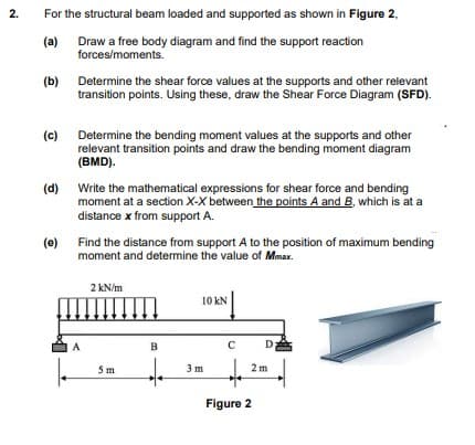
Transcribed Image Text:For the structural beam loaded and supported as shown in Figure 2,
(a)
Draw a free body diagram and find the support reaction
forces/moments.
(b)
Determine the shear force values at the supports and other relevant
transition points. Using these, draw the Shear Force Diagram (SFD).
(c)
Determine the bending moment values at the supports and other
relevant transition points and draw the bending moment diagram
(BMD).
(d) Write the mathematical expressions for shear force and bending
moment at a section X-X between the points A and B, which is at a
distance x from support A.
(e)
Find the distance from support A to the position of maximum bending
moment and determine the value of Mmax.
2 kN/m
10 kN
A
B
D
5m
3 m
2 m
Figure 2
2.
Expert Solution
This question has been solved!
Explore an expertly crafted, step-by-step solution for a thorough understanding of key concepts.

Step by step
Solved in 4 steps with 3 images

Knowledge Booster


Learn more about
Need a deep-dive on the concept behind this application? Look no further. Learn more about this topic, mechanical-engineering and related others by exploring similar questions and additional content below.Recommended textbooks for you
Mechanics of Materials (MindTap Course List)
Mechanical Engineering
ISBN:
9781337093347
Author:
Barry J. Goodno, James M. Gere
Publisher:
Cengage Learning
Mechanics of Materials (MindTap Course List)
Mechanical Engineering
ISBN:
9781337093347
Author:
Barry J. Goodno, James M. Gere
Publisher:
Cengage Learning