Full Adder Truth Table, cont. 0 0CI80)o work,return enter 101180) 1.0 tail shift 10(181)0 +||+1=|1| 1 CIB)O 2-3) Design a full adder circuit using two ICs: 7486 and 7400. Modify the logic diagram from 2-1). Trace variables A, B, Cin through gates to find output functions E and Cou. Use DeMorgan's Laws to verify that your output functions are the same as in the original diagram 2-1). C and pin numbers on your diagram d columns in |13). Write IC and pin numbers on your l lifcuit for proper output by filling in the gray-shaded columns aH Adder Truth Table. Describe any debugging you do. Keep your circuit built for the next part – you will only need to modify it! Part 2. Full Adder 2-1) Now consider the logic symbol, Σ 2 Input bits Σ Sum Output carry Cout Cin Input carry as well as the logic symbol consisting of two half adders combined: 2 half adders Combined to build Half-adder Half-adder Σ Σ ΑΘΒ Σ Sum Σ (A O B) O Cin Cout Cout Full Adder (A O B)Cin Input carry, Cin OR Output carry, Cout AB AB+ (A O B)Cn 3 6. Adders and Subtractors Expt. Tech 1505
Full Adder Truth Table, cont. 0 0CI80)o work,return enter 101180) 1.0 tail shift 10(181)0 +||+1=|1| 1 CIB)O 2-3) Design a full adder circuit using two ICs: 7486 and 7400. Modify the logic diagram from 2-1). Trace variables A, B, Cin through gates to find output functions E and Cou. Use DeMorgan's Laws to verify that your output functions are the same as in the original diagram 2-1). C and pin numbers on your diagram d columns in |13). Write IC and pin numbers on your l lifcuit for proper output by filling in the gray-shaded columns aH Adder Truth Table. Describe any debugging you do. Keep your circuit built for the next part – you will only need to modify it! Part 2. Full Adder 2-1) Now consider the logic symbol, Σ 2 Input bits Σ Sum Output carry Cout Cin Input carry as well as the logic symbol consisting of two half adders combined: 2 half adders Combined to build Half-adder Half-adder Σ Σ ΑΘΒ Σ Sum Σ (A O B) O Cin Cout Cout Full Adder (A O B)Cin Input carry, Cin OR Output carry, Cout AB AB+ (A O B)Cn 3 6. Adders and Subtractors Expt. Tech 1505

Chapter22: Sequence Control
Section: Chapter Questions
Problem 6SQ: Draw a symbol for a solid-state logic element AND.

Related questions

Question
how do i draw 2-3
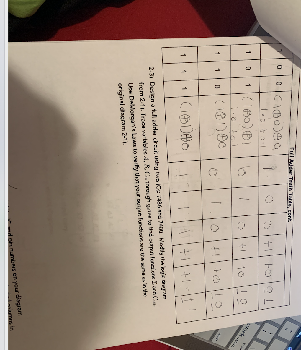
Transcribed Image Text:Full Adder Truth Table, cont.
0 0CI80)o
work,return
enter
101180)
1.0 tail
shift
10(181)0
+||+1=|1|
1 CIB)O
2-3) Design a full adder circuit using two ICs: 7486 and 7400. Modify the logic diagram
from 2-1). Trace variables A, B, Cin through gates to find output functions E and Cou.
Use DeMorgan's Laws to verify that your output functions are the same as in the
original diagram 2-1).
C and pin numbers on your diagram
d columns in
Transcribed Image Text:|13). Write IC and pin numbers on your
l lifcuit for proper output by filling in the gray-shaded columns
aH Adder Truth Table. Describe any debugging you do. Keep your circuit built
for the next part – you will only need to modify it!
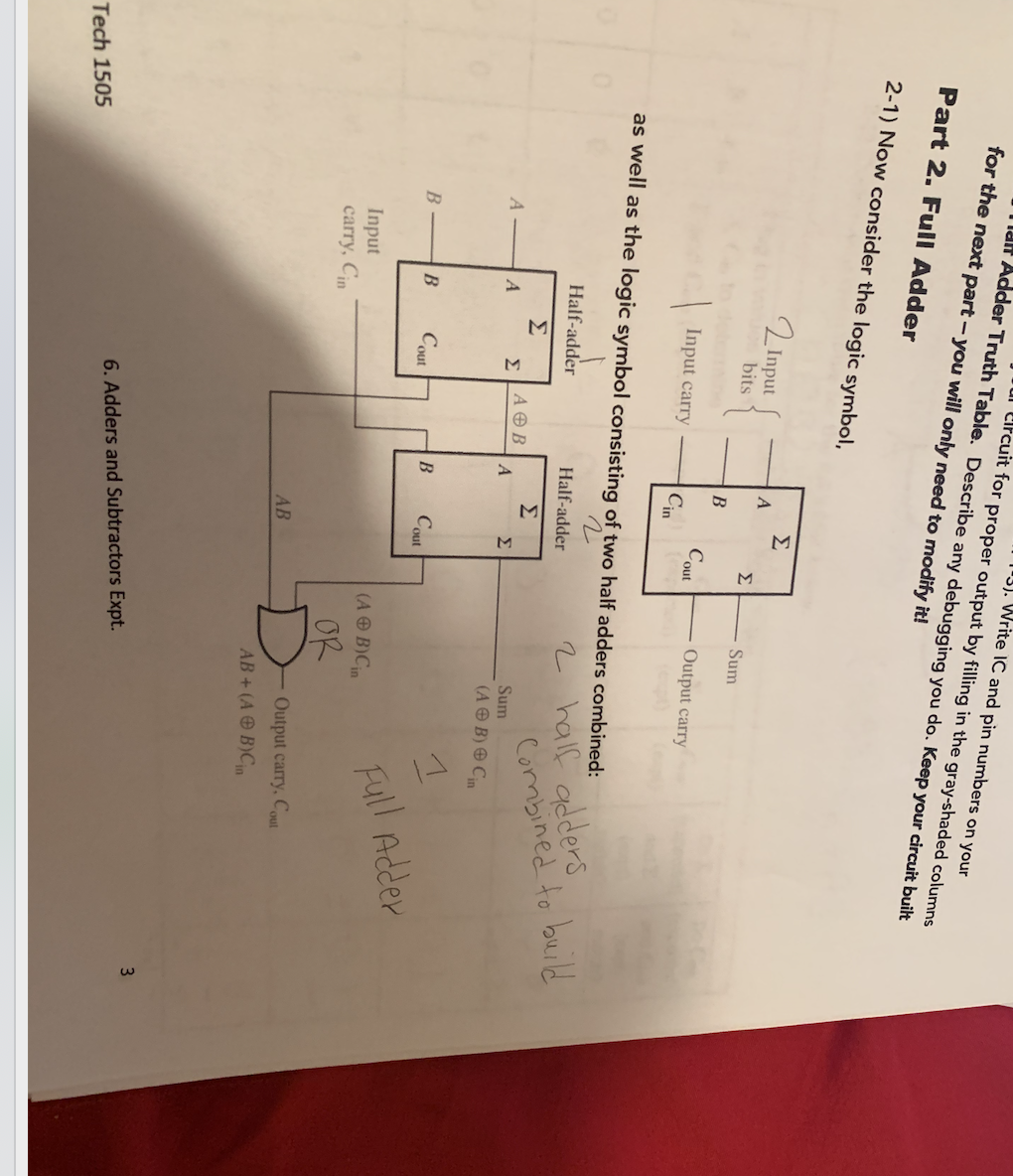
Part 2. Full Adder
2-1) Now consider the logic symbol,
Σ
2 Input
bits
Σ
Sum
Output carry
Cout
Cin
Input carry
as well as the logic symbol consisting of two half adders combined:
2 half adders
Combined to build
Half-adder
Half-adder
Σ
Σ
ΑΘΒ
Σ
Sum
Σ
(A O B) O Cin
Cout
Cout
Full Adder
(A O B)Cin
Input
carry, Cin
OR
Output carry, Cout
AB
AB+ (A O B)Cn
3
6. Adders and Subtractors Expt.
Tech 1505
Expert Solution
This question has been solved!
Explore an expertly crafted, step-by-step solution for a thorough understanding of key concepts.

This is a popular solution!

Trending now
This is a popular solution!

Step by step
Solved in 2 steps with 2 images

Knowledge Booster


Learn more about
Need a deep-dive on the concept behind this application? Look no further. Learn more about this topic, electrical-engineering and related others by exploring similar questions and additional content below.Recommended textbooks for you