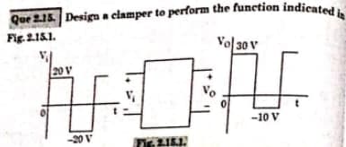
Que 2.15. Design a clamper to perform the function indicated i Fig. 2.15.1. 20 V Vol 30 V DA V. -10 V


Q: 5-Apply KVL to find the voltage V4 across R4 from the circuit shown below. R₁ V₁ =12V 100V R5 R₂ WW…
A: Given circuit:
Q: 1. Consider a half-wave rectifier circuit of Fig 5 with a resistive load of 25 Nand a 60 Hz ac…
A:
Q: > FIND THE TOTAL POWER OF THE CHT. R 朝 عي 22 03 章 本 2/2 册 2 级 ¥102
A: Given data: Input current to the circuit, I = 3 A Resistor network as follows, To find: Power of…
Q: (+1) Vs 6Ω 3Ω 2Ω ww |.
A: Given data, Vs=5 V, Is=10 A Circuit diagram is given as,
Q: Diiferentiate open loop system and close loop system
A: The desired output in an open loop system is independent of the control action, which is one of the…
Q: In an ideal op-amp, which is not true? a) Open loop voltage gain is infinite b) Input resistance is…
A: The correct option along with the explanation has been provided in the following section.
Q: a) i) Consider the AM signal s(t) = [4+3cos(1000mt)]cos (20000mt). Calculate its bandwidth and the…
A:
Q: Which is the correct expression for lout for the circuit shown here (you can assume that the two…
A:
Q: alculate the current passing through the 1502 resistor using Thevenin's heorem. 12V 1002 1292 1552…
A:
Q: A closed loop system has the characteristic equation given by s³ + Ks² + (K + 2)s +3= 0. For this…
A: Given, A closed loop system has characteristics equation, s3+Ks2+K+2s+3=0
Q: Que 4.28. On short circuit tests, the currents and voltages were determined experimentally for an…
A: The two port network is used to simply the larger network into equivalent two port model.
Q: QUESTION 8 What is the equivalent re F N 45 5V + dc(5)
A: Given data, Given circuit diagram is,
Q: Consider the design of a low frequency differentiator to achieve the differentiation gain K = 0.001,…
A: Given data, Highest frequency fH=1000 Hz Capacitance C=0.1 μF Frequency fb=10fh
Q: Problem 1. Consider a half-wave rectifier circuit with a resistive load of 25 Ωand a 60 Hz ac…
A:
Q: Let u = (-1, 3), v = (2, 4), and w = (2, -5). Find the component form of the vector a) u + v b) u -…
A:
Q: Show complete solution. Using Kirchhoff's circuit laws, find a. l₁ b. 1₂ C. 13 d. 14 e. Is
A: Given:
Q: EX- Given a telephone TL of loo mile long has 76=685-192 2=0.00497 Neper /mile and •352 rad /mik at…
A: Given data: The length of the transmission line l=100 mile Z0=685-j92 Ωα=0.00497 NP/Mileβ=0.0352…
Q: The Boolean expression AB + AC + BC simplifies to
A: Given Boolean expression, F=AB+AC'+BC
Q: Find mesh currents and the power of the current source. 12 V 90 ww ॥ ਨੂੰ 20 3 A 60
A: Consider the given circuit:
Q: Calculate each of the circuit parameters for the provided circuit. RT(K2) = Is(mA) = %3D V1(M = (mA)…
A: Given: Circuit diagram
Q: a) Design 5th-order low-pass FIR filter with cut-off frequency we using the rectangular window. b)…
A: Since you have asked multiple questions, we will solve the first question for you. If you want any…
Q: Write a Matlab code to sketch using plot function, y(t)=3 sin(t) for 3 periods
A: The required Matlab code can be written with help of a predefined sine function. In order to plot…
Q: Fig. Shows a parallel circuit. Determine the power absorbed by each load and the total complex…
A:
Q: c) A subcarrier is a modulated carrier signal at a lower frequency that is combined with the main…
A: Given data, Frequency of the subcarrier fsc=70 kHz Tones, fm1=2.1 kHzfm2=6.8 kHz Carrier frequency…
Q: 13) The transfer function of a system is given as 81/ (s^2 + 16s +81). Find the undamped natural…
A:
Q: An apparatus that converts analog data into its digital equivalent is referred to as a digitizer.…
A: Given: Digitizer: Digitizer is an apparatus used to convert the analog data into digital data. It is…
Q: 13. The purpose of the __________ is to periodically sample the continually changing analog signal…
A: 1) The purpose of the quantisation is to periodically sample the continually changing analog signal…
Q: 1. A certain voltage doubler has 20 Vrms on its input. What is the output voltage? Draw the circuit,…
A:
Q: The unity feedback system with OLTF is (s+2) given by GH(s) = s(s+1)(s+7). The steady state error…
A: Given, The unity feedback system with open loop transfer function, GHs=s+2ss+1s+7
Q: (c) A TV broadcast antenna transmits power of 3 kW at frequency of 200 MHz. The transmitter antenna…
A: “Since you have posted a question with multiple sub-parts, we will solve the first three sub-parts…
Q: for the following AC signal: x(t)=3cos(2000 t), the root mean square value is ************
A: Given, The AC signal is xt=3cos2000πt
Q: What is the basic working principle of wavelength division multiplexing?
A: Using a technology called wavelength division multiplexing (WDM), several optical carrier signals…
Q: 5. In the figure shown, if the atmospheric pressure is 101.03 kPa and the absolute at the bottom of…
A: 5) It is given that: Pb=3 kPaPatm=101.03 kPa
Q: Derive a minimum Sum of Products (SOP) expression for the logic function given below. You may use…
A: Given a logic function, FA,B,C,D=∑m3,4,5,6,7,10,11,14,15
Q: Given Ix = 1.8 A, calculate the unknown current lo. -3A X Iv 2A
A: Given network figure, Here, Ix=1.8 A
Q: 3) Determine the inductance of the magnetic actuator (figure 1) when the plunger is a 1/3 of the way…
A: The given figure is shown below. The plunger is 13 of the way in the gap. MMF is Fm=199.5 A turns.…
Q: ompute the value of the apparent power, reactive power, real power and its power factor. 25-52 WWW.…
A: Given parameters: A Series RLC circuit, Resistor, R = 25 ohm Inductor, L = 0.08 H Capacitor, C = 42…
Q: Instructions a. Show your designed circuit b. Show the Load voltages in phase a, b and c c. Show the…
A: Since it is asked to show only calculations, so we will solve only subpart (e). Because it is only…
Q: The speed of a 100 MW alternator drops by 4% from no load to full load. (a) Find the speed…
A: We have an alternator with, Rating = 100 MW Speed drops from no load to full load = 4% From this…
Q: A 35KVA, transformer has 50 Hz frequency input with voltage values given as 300/220V, with primary…
A: Given data, A transformer has S=35 kVAf=50 hzV1/V2=300/220 VN1=550
Q: Q3: Find the bit error probability of 1200 baud coherent 32-PSK if the available signal power at…
A: According to policy first question to be answered Q 3 In coherent 32-PSK, the bit error…
Q: figure 5 A With the help of the tiand theary only distinguish between an insulator and a…
A: Note: We are authorized to answer one question at a time, since you have not mentioned which…
Q: Two balanced, parallel connected loads are connected to a 50 Hz, 300 V, three-phase supply. The…
A:
Q: Pulse-amplitude modulation signals are multiplexed by using: a. subcarriers b. A/D converters c.…
A:
Q: 3. The __________ is, in essence, a switch which closes for a brief period of time and then open,…
A: 3. The relays is, in essence, a switch which closes for a brief period oftime and then open, closing…
Q: Multi-Source Circuit Analysis 3 Consider the circuit shown with the following parameters: 4₁ = 10 A…
A:
Q: Calculate the electric and magnetic fields produced by the radiation coming from 200W bulb at a…
A:
Q: Example: Sketch the single-sided and double-sided spectra of (10nt - 1) x(t) = 2 sin (10nt
A: Given: xt=2sin10πt-π6
Q: 0 B XOR A AND A' A What logic function does the circuit shown implement? XNOR OR NAND NOR F
A: Given diagram,
Q: solve this
A: We have to find the Laplace transform of e-atcosωtLcosωt=ss2+ω2We will use the complex shift…

Step by step
Solved in 2 steps with 1 images


- A pure resistive R ohm resistor to the output of the three phase Bridge Rectifier connected and provides 250 DC output voltage, 50A load current, welding frequency 50 Hertz. a-Efficiency=? b-FF Coefficient c-RF CoefficientDevices that pass the signal from its source to the measurement device without aphysical connection by using transformer, optical or capacitive coupling technique arecalled?Select one a. bridgesb. isolatorsc.filters d.rectifiersof a Flyback converter with Circuit parameters given below.Circuit Parameters;Input Voltage Vs= 48 VN1/N2=3Lm=500 μHR=5ΩC=200 μFSwitching frequency f=40 kHzOutput Voltage Vo=10 Va) Duty Cycleb) In terms of magnetization inductor (Lm); mean, maximum andtheir minimum values;c) Find the output voltage fluctuation. (All components are ideal.assume.)
- Q. The IC used in OPAMP is LM 741. True FalseFind the performance parameters (FF, RF and n) for the Single phase bridge uncontrolled rectifier with RL load. If the phase voltage: Vph(t) = Vm sin(wt). Draw the circuit diagram and sketch the voltages and current waveforms.A. Determine V1 without C B. Determine V1 and VR with C C. From aB Determine V2, IL, PD D. From B determine the efficiency of the regulator (OUR SUBJECT IS INDUSTRIAL ELECTRONIC)
- A group of UTAS-Nizwa students are working on a project entitled "Gas leak detector alarm" for their final year in Diploma level. The circuit works on DC voltage of 16 volts and DC current of 7 milliampere. Students need to design a power supply circuit for their project. Consider an RMS voltage input of 220 volt, 60 Hz. Using a Full Wave Bridge Rectifier with Transformer, Silicon diode and Capacitor Filter, Design the power supply. a. Compute for the load resistance, peak output voltage, input peak voltage to the diodes (secondary voltage), peak input voltage and the turns ratio of the transformer. 1. What is the value of the load resistance? b. Draw the Power Supply circuit (capacitor filter connected in parallel with the resistor) and write the computed values (No value for the capacitor).Make the control circuit made up of a TRIAC and an optocoupler, for one: 2000W lamp, 120vac You must choose from the following elements: optocoupler: OPTO 1: MOC3021 OPTO 2: MOC3051 Transistor: TRIAC 1:Q20115L5 TRIAC2:Q2025R5With a neat diagram ,explain about the working of Dual Slope ADC.
- answer all subparts A three phase, 12 pulse rectifier is fed from a transformer with effective turns ratio of 0.5, the primary L-L voltage of the supply is 400kV, ignition delay angle is 30 degree, overlap angle is 15 degree, and the dc link current is 2kA, find the values of all the quantities in relation to this question Q1) the DC link voltage at no load (Vdo) at rectifier end is (kv) 560 540 500 468 Q2) the value of Vdc at the rectifier terminals is close to (kV) 560 540 424 464 Q3) the total reactive power that needs to be supplied at rectifier end is close to................... MVAR 667 356 456 978 Q4) the fundamental component of ac current is......... (kA) 2.1 2.89 1.98 1.56a) What type of filters is used in Rectifiers? Briefly explain working of each with the help of circuit diagram. b) What is Clipper? Briefly explain its types with help of circuit diagram. c) What is clamper? Briefly explain its working.P 3.15)A single-phase bridge rectifier is supplied from a 220-V, 60-Hz source. The load resistance is RL = 300 Ω. (a) Design a C-filter so that the ripple factor of the output voltage is less than 3%. (b) With the value of capacitor Ce in part (a), calculate the average load voltage Vdc