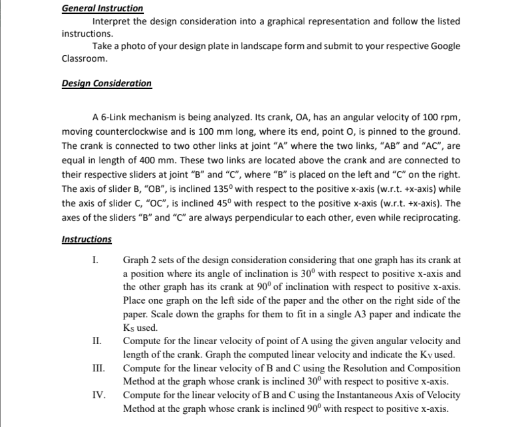
General Instruction instructions. Interpret the design consideration into a graphical representation and follow the listed Take a photo of your design plate in landscape form and submit to your respective Google Classroom. Design Consideration A 6-Link mechanism is being analyzed. Its crank, OA, has an angular velocity of 100 rpm, moving counterclockwise and is 100 mm long, where its end, point O, is pinned to the ground. The crank is connected to two other links at joint "A" where the two links, "AB" and "AC", are equal in length of 400 mm. These two links are located above the crank and are connected to their respective sliders at joint "B" and "C", where "B" is placed on the left and "C" on the right. The axis of slider B, "OB", is inclined 135° with respect to the positive x-axis (w.r.t. +x-axis) while the axis of slider C, "OC", is inclined 45° with respect to the positive x-axis (w.r.t. +x-axis). The axes of the sliders "B" and "C" are always perpendicular to each other, even while reciprocating. Instructions I. II. III. IV. Graph 2 sets of the design consideration considering that one graph has its crank at a position where its angle of inclination is 30° with respect to positive x-axis and the other graph has its crank at 90° of inclination with respect to positive x-axis. Place one graph on the left side of the paper and the other on the right side of the paper. Scale down the graphs for them to fit in a single A3 paper and indicate the Ks used. Compute for the linear velocity of point of A using the given angular velocity and length of the crank. Graph the computed linear velocity and indicate the Ky used. Compute for the linear velocity of B and C using the Resolution and Composition Method at the graph whose crank is inclined 30° with respect to positive x-axis. Compute for the linear velocity of B and C using the Instantaneous Axis of Velocity Method at the graph whose crank is inclined 90° with respect to positive x-axis.
General Instruction instructions. Interpret the design consideration into a graphical representation and follow the listed Take a photo of your design plate in landscape form and submit to your respective Google Classroom. Design Consideration A 6-Link mechanism is being analyzed. Its crank, OA, has an angular velocity of 100 rpm, moving counterclockwise and is 100 mm long, where its end, point O, is pinned to the ground. The crank is connected to two other links at joint "A" where the two links, "AB" and "AC", are equal in length of 400 mm. These two links are located above the crank and are connected to their respective sliders at joint "B" and "C", where "B" is placed on the left and "C" on the right. The axis of slider B, "OB", is inclined 135° with respect to the positive x-axis (w.r.t. +x-axis) while the axis of slider C, "OC", is inclined 45° with respect to the positive x-axis (w.r.t. +x-axis). The axes of the sliders "B" and "C" are always perpendicular to each other, even while reciprocating. Instructions I. II. III. IV. Graph 2 sets of the design consideration considering that one graph has its crank at a position where its angle of inclination is 30° with respect to positive x-axis and the other graph has its crank at 90° of inclination with respect to positive x-axis. Place one graph on the left side of the paper and the other on the right side of the paper. Scale down the graphs for them to fit in a single A3 paper and indicate the Ks used. Compute for the linear velocity of point of A using the given angular velocity and length of the crank. Graph the computed linear velocity and indicate the Ky used. Compute for the linear velocity of B and C using the Resolution and Composition Method at the graph whose crank is inclined 30° with respect to positive x-axis. Compute for the linear velocity of B and C using the Instantaneous Axis of Velocity Method at the graph whose crank is inclined 90° with respect to positive x-axis.

Elements Of Electromagnetics
7th Edition
ISBN:9780190698614
Author:Sadiku, Matthew N. O.
Publisher:Sadiku, Matthew N. O.
ChapterMA: Math Assessment
Section: Chapter Questions
Problem 1.1MA

Related questions

Question
100%
Please help me answer this, I just need the interpretation of this or how to draw this given the instructions. Pleasee, show me how you draw this, thank you in advance!
Transcribed Image Text:General Instruction
instructions.
Interpret the design consideration into a graphical representation and follow the listed
Take a photo of your design plate in landscape form and submit to your respective Google
Classroom.
Design Consideration
A 6-Link mechanism is being analyzed. Its crank, OA, has an angular velocity of 100 rpm,
moving counterclockwise and is 100 mm long, where its end, point O, is pinned to the ground.
The crank is connected to two other links at joint "A" where the two links, "AB" and "AC", are
equal in length of 400 mm. These two links are located above the crank and are connected to
their respective sliders at joint "B" and "C", where "B" is placed on the left and "C" on the right.
The axis of slider B, "OB", is inclined 135° with respect to the positive x-axis (w.r.t. +x-axis) while
the axis of slider C, "OC", is inclined 45° with respect to the positive x-axis (w.r.t. +x-axis). The
axes of the sliders "B" and "C" are always perpendicular to each other, even while reciprocating.
Instructions
I.
II.
III.
IV.
Graph 2 sets of the design consideration considering that one graph has its crank at
a position where its angle of inclination is 30° with respect to positive x-axis and
the other graph has its crank at 90° of inclination with respect to positive x-axis.
Place one graph on the left side of the paper and the other on the right side of the
paper. Scale down the graphs for them to fit in a single A3 paper and indicate the
Ks used.
Compute for the linear velocity of point of A using the given angular velocity and
length of the crank. Graph the computed linear velocity and indicate the Ky used.
Compute for the linear velocity of B and C using the Resolution and Composition
Method at the graph whose crank is inclined 30° with respect to positive x-axis.
Compute for the linear velocity of B and C using the Instantaneous Axis of Velocity
Method at the graph whose crank is inclined 90° with respect to positive x-axis.
Expert Solution
This question has been solved!
Explore an expertly crafted, step-by-step solution for a thorough understanding of key concepts.

This is a popular solution!

Trending now
This is a popular solution!

Step by step
Solved in 5 steps with 18 images

Knowledge Booster


Learn more about
Need a deep-dive on the concept behind this application? Look no further. Learn more about this topic, mechanical-engineering and related others by exploring similar questions and additional content below.Recommended textbooks for you
Elements Of Electromagnetics
Mechanical Engineering
ISBN:
9780190698614
Author:
Sadiku, Matthew N. O.
Publisher:
Oxford University Press

Mechanics of Materials (10th Edition)
Mechanical Engineering
ISBN:
9780134319650
Author:
Russell C. Hibbeler
Publisher:
PEARSON

Thermodynamics: An Engineering Approach
Mechanical Engineering
ISBN:
9781259822674
Author:
Yunus A. Cengel Dr., Michael A. Boles
Publisher:
McGraw-Hill Education
Elements Of Electromagnetics
Mechanical Engineering
ISBN:
9780190698614
Author:
Sadiku, Matthew N. O.
Publisher:
Oxford University Press
Mechanics of Materials (10th Edition)
Mechanical Engineering
ISBN:
9780134319650
Author:
Russell C. Hibbeler
Publisher:
PEARSON
Thermodynamics: An Engineering Approach
Mechanical Engineering
ISBN:
9781259822674
Author:
Yunus A. Cengel Dr., Michael A. Boles
Publisher:
McGraw-Hill Education

Control Systems Engineering
Mechanical Engineering
ISBN:
9781118170519
Author:
Norman S. Nise
Publisher:
WILEY

Mechanics of Materials (MindTap Course List)
Mechanical Engineering
ISBN:
9781337093347
Author:
Barry J. Goodno, James M. Gere
Publisher:
Cengage Learning

Engineering Mechanics: Statics
Mechanical Engineering
ISBN:
9781118807330
Author:
James L. Meriam, L. G. Kraige, J. N. Bolton
Publisher:
WILEY