he following amplifier (consider the case with a R_L load) consists of a channel JFET n. In the amplifier, the value of the DC source ({+ V} DD = 20 V) and of all resistors (shown in the schematic) and capacitors ( C1= C2= 20 µF) is known. At the same time, the JFET has the following specifications: IDSS= 10 mA and Vp= -3.5 V. The output resistance of the JFET is r_d = infinityΩ. AC analysis: The input signal VS is a small sinusoidal signal, at the same time it oscillates at a medium frequency, in such a way that the response is not affected by the capacitances. Get the circuit in small signal and do all the necessary procedure / demonstration. To determine: A) The transconductance  gm at the operating point. B) The small signal equivalent circuit drawn conveniently.

Introductory Circuit Analysis (13th Edition)
13th Edition
ISBN:9780133923605
Author:Robert L. Boylestad
Publisher:Robert L. Boylestad
Chapter1: Introduction
Section: Chapter Questions
Problem 1P: Visit your local library (at school or home) and describe the extent to which it provides literature...
icon
Related questions
Question

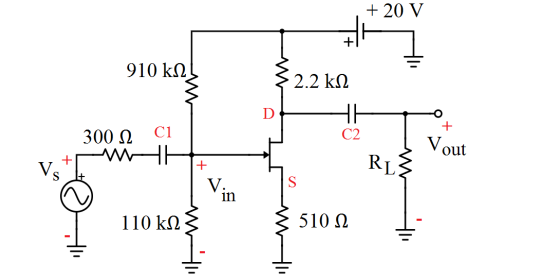
The following amplifier (consider the case with a R_L load) consists of a channel JFET n. In the amplifier, the value of the DC source ({+ V} DD = 20 V) and of all resistors (shown in the schematic) and capacitors ( C1= C2= 20 µF) is known. At the same time, the JFET has the following specifications: IDSS= 10 mA and Vp= -3.5 V. The output resistance of the JFET is r_d = infinityΩ.
AC analysis:
The input signal VS is a small sinusoidal signal, at the same time it oscillates at a medium frequency, in such a way that the response is not affected by the capacitances. Get the circuit in small signal and do all the necessary procedure / demonstration. To determine:
A) The transconductance  gm at the operating point.
B) The small signal equivalent circuit drawn conveniently.

+ 20 V
910 kn
2.2 kN
300 N Ci
Vout
RL
+1
V:.
in
110 kΩ)
510 N
Transcribed Image Text:+ 20 V 910 kn 2.2 kN 300 N Ci Vout RL +1 V:. in 110 kΩ) 510 N
Expert Solution
steps

Step by step

Solved in 4 steps with 4 images

Blurred answer
Knowledge Booster
Source transformation method
Learn more about
Need a deep-dive on the concept behind this application? Look no further. Learn more about this topic, electrical-engineering and related others by exploring similar questions and additional content below.
Similar questions
  • SEE MORE QUESTIONS
Recommended textbooks for you
Introductory Circuit Analysis (13th Edition)
Electrical Engineering
ISBN:
9780133923605
Author:
Robert L. Boylestad
Publisher:
PEARSON
Delmar's Standard Textbook Of Electricity
Electrical Engineering
ISBN:
9781337900348
Author:
Stephen L. Herman
Publisher:
Cengage Learning
Programmable Logic Controllers
Electrical Engineering
ISBN:
9780073373843
Author:
Frank D. Petruzella
Publisher:
McGraw-Hill Education
Fundamentals of Electric Circuits
Electrical Engineering
ISBN:
9780078028229
Author:
Charles K Alexander, Matthew Sadiku
Publisher:
McGraw-Hill Education
Electric Circuits. (11th Edition)
Electrical Engineering
ISBN:
9780134746968
Author:
James W. Nilsson, Susan Riedel
Publisher:
PEARSON
Engineering Electromagnetics
Electrical Engineering
ISBN:
9780078028151
Author:
Hayt, William H. (william Hart), Jr, BUCK, John A.
Publisher:
Mcgraw-hill Education,