How many 1/2 inch diameter hole that can be punch in one motion of a 1/8 inch thick plate using a force of 50 tons. The ultimate shear stress is 52 ksi and factor of safety of 3. A. 7 B. 9 C. 8 D. 10
How many 1/2 inch diameter hole that can be punch in one motion of a 1/8 inch thick plate using a force of 50 tons. The ultimate shear stress is 52 ksi and factor of safety of 3. A. 7 B. 9 C. 8 D. 10

Elements Of Electromagnetics
7th Edition
ISBN:9780190698614
Author:Sadiku, Matthew N. O.
Publisher:Sadiku, Matthew N. O.
ChapterMA: Math Assessment
Section: Chapter Questions
Problem 1.1MA

Related questions
Question
100%
How many 1/2 inch diameter hole that can be punch in one motion of a 1/8 inch thick plate
using a force of 50 tons. The ultimate shear stress is 52 ksi and factor of safety of 3.
A. 7 B. 9 C. 8 D. 10
Refer Machine Elements and Stresses Equations from the figure. Please solve the Problem elaborately. Your solution will be use as reference for my studies. Thank you so much your work will be appreciated much!
Transcribed Image Text:V1
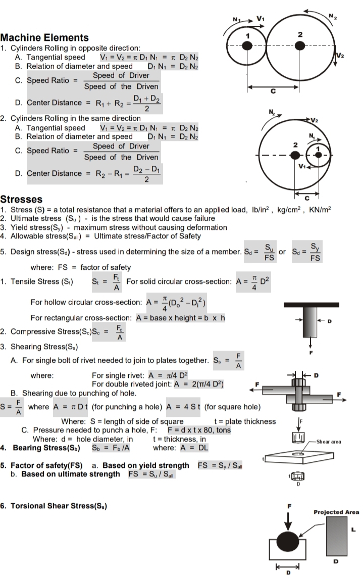
Machine Elements
1. Cylinders Rolling in opposite direction:
Á. Tangential speed
B. Relation of diameter and speed
V, = V2 = T D, N, = r D2 N2
DI N1 = D2 N2
Speed of Driver
C. Speed Ratio =
Speed of the Driven
D. Center Distance = R, + R2 =
D, + D2
2. Cylinders Rolling in the same direction
Vi = V2 = n D, N; = n D2 N2
D, N1 = D2 N2
A. Tangential speed
B. Relation of diameter and speed
Speed of Driver
Speed of the Driven
D2 - D1
C. Speed Ratio =
D. Center Distance = R2 -R, =
Stresses
1. Stress (S) = a total resistance that a material offers to an applied load, Ib/in? , kg/cm² , KN/m?
2. Ultimate stress (Su ) - is the stress that would cause failure
3. Yield stress(Sy) - maximum stress without causing deformation
4. Allowable stress(Sal) = Ultimate stress/Factor of Safety
Sy
5. Design stress(Sa) - stress used in determining the size of a member. Sa =
or Sa =
FS
FS
where: FS = factor of safety
1. Tensile Stress (S.)
S =
For solid circular cross-section: A =
A
D2
#0,² -D²)
For hollow circular cross-section: A =
For rectangular cross-section: A = base x height = b x h
Fa
2. Compressive Stress(Sc)S. =
A
3. Shearing Stress(S.)
F
A. For single bolt of rivet needed to join to plates together. S, =
For single rivet: A = t/4 D²
For double riveted joint: A = 2(TT/4 D²)
where:
D
B. Shearing due to punching of hole.
S =
where A = 1 Dt (for punching a hole) A = 4 St (for square hole)
Where: S = length of side of square
C. Pressure needed to punch a hole, F: F = d x t x 80, tons
t = plate thickness
t = thickness, in
where: A = DL
Where: d = hole diameter, in
-Shear area
4. Bearing Stress(Sb)
Sp = Fb IA
a. Based on yield strength FS = Sy / Sall
5. Factor of safety(FS)
b. Based on ultimate strength FS = S,/ Sall
D
6. Torsional Shear Stress(Ss)
Projected Area
D
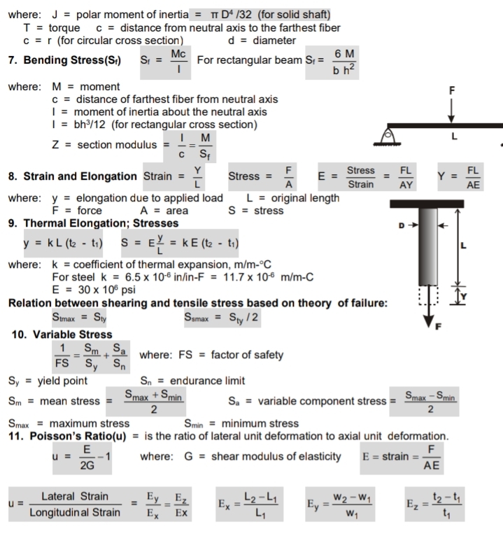
Transcribed Image Text:where: J = polar moment of inertia = T Dª /32 (for solid shaft)
c = distance from neutral axis to the farthest fiber
T = torque
c = r (for circular cross section)
7. Bending Stress(S:) Si =
d = diameter
For rectangular beam S = 6 M
b h?
Mc
where: M = moment
F
c = distance of farthest fiber from neutral axis
| = moment of inertia about the neutral axis
| = bh/12 (for rectangular cross section)
I M
c Sf
L
Z = section modulus
Y
8. Strain and Elongation Strain =
Stress
FL
Stress =
A
E
Strain
FL
Y =
AE
AY
where: y = elongation due to applied load
L = original length
F = force
A = area
S = stress
9. Thermal Elongation; Stresses
y = kL (t2 - t1) S = E! = kE (t2 - t1)
where: k = coeficient of thermal expansion, m/m-°C
For steel k = 6.5 x 10⁻⁶ in/in-F = 11.7 x 10⁶ m/m-C
E = 30 x 10° psi
Relation between shearing and tensile stress based on theory of failure:
Samax = Sty /2
Smax = Sty
10. Variable Stress
1 Sm Sa
FS Sy S,
Sy = yield point
where: FS = factor of safety
Sn = endurance limit
Smax + Smin
S. = variable component stress =
Smax - Smin
Sm = mean stress =
2
2
Smax = maximum stress
11. Poisson's Ratio(u) = is the ratio of lateral unit deformation to axial unit deformation.
Smin = minimum stress
E
F
E = strain =-
AE
where: G = shear modulus of elasticity
2G
W2 – W1
Ey
t2 - ty
Lateral Strain
Ey Ez
Ex
L2 -L,
Ex
L1
Ez
Longitudin al Strain
Ex
t,
Expert Solution
This question has been solved!
Explore an expertly crafted, step-by-step solution for a thorough understanding of key concepts.

This is a popular solution!

Trending now
This is a popular solution!

Step by step
Solved in 2 steps with 1 images

Recommended textbooks for you
Elements Of Electromagnetics
Mechanical Engineering
ISBN:
9780190698614
Author:
Sadiku, Matthew N. O.
Publisher:
Oxford University Press

Mechanics of Materials (10th Edition)
Mechanical Engineering
ISBN:
9780134319650
Author:
Russell C. Hibbeler
Publisher:
PEARSON

Thermodynamics: An Engineering Approach
Mechanical Engineering
ISBN:
9781259822674
Author:
Yunus A. Cengel Dr., Michael A. Boles
Publisher:
McGraw-Hill Education
Elements Of Electromagnetics
Mechanical Engineering
ISBN:
9780190698614
Author:
Sadiku, Matthew N. O.
Publisher:
Oxford University Press
Mechanics of Materials (10th Edition)
Mechanical Engineering
ISBN:
9780134319650
Author:
Russell C. Hibbeler
Publisher:
PEARSON
Thermodynamics: An Engineering Approach
Mechanical Engineering
ISBN:
9781259822674
Author:
Yunus A. Cengel Dr., Michael A. Boles
Publisher:
McGraw-Hill Education

Control Systems Engineering
Mechanical Engineering
ISBN:
9781118170519
Author:
Norman S. Nise
Publisher:
WILEY

Mechanics of Materials (MindTap Course List)
Mechanical Engineering
ISBN:
9781337093347
Author:
Barry J. Goodno, James M. Gere
Publisher:
Cengage Learning

Engineering Mechanics: Statics
Mechanical Engineering
ISBN:
9781118807330
Author:
James L. Meriam, L. G. Kraige, J. N. Bolton
Publisher:
WILEY