(i) (ii) Draw a half-wave rectifier circuit with a diode which produces a negative output voltage waveform from the following input AC waveform: Vin = 10 sin(10nt) V. In a voltage versus time graph sketch the input and output voltages waveforms. You should show at least 2 periods of the input and output voltage signals, the peak values of the input and output signals and the period of these signals in seconds. Consider that the diode's cut-in voltage (starts to conduct), V is 0.7 V.
(i) (ii) Draw a half-wave rectifier circuit with a diode which produces a negative output voltage waveform from the following input AC waveform: Vin = 10 sin(10nt) V. In a voltage versus time graph sketch the input and output voltages waveforms. You should show at least 2 periods of the input and output voltage signals, the peak values of the input and output signals and the period of these signals in seconds. Consider that the diode's cut-in voltage (starts to conduct), V is 0.7 V.

Chapter59: Motor Startup And Troubleshooting Basics
Section: Chapter Questions
Problem 12SQ: How is a solid-state diode tested? Explain.

Related questions
Question
Transcribed Image Text:(i)
(ii)
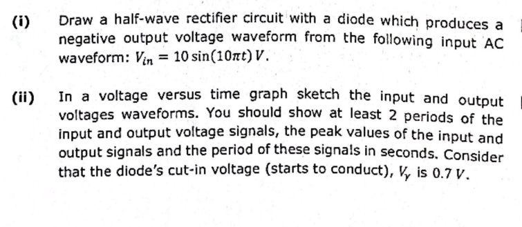
Draw a half-wave rectifier circuit with a diode which produces a
negative output voltage waveform from the following input AC
waveform: Vin = 10 sin(10nt) V.
In a voltage versus time graph sketch the input and output
voltages waveforms. You should show at least 2 periods of the
input and output voltage signals, the peak values of the input and
output signals and the period of these signals in seconds. Consider
that the diode's cut-in voltage (starts to conduct), V is 0.7 V.
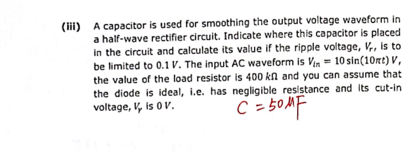
Transcribed Image Text:(iii) A capacitor is used for smoothing the output voltage waveform in
a half-wave rectifier circuit. Indicate where this capacitor is placed
in the circuit and calculate its value if the ripple voltage, Vr, is to
be limited to 0.1 V. The input AC waveform is Vin = 10 sin(10nt) V,
the value of the load resistor is 400 kn and you can assume that
the diode is ideal, i.e. has negligible resistance and its cut-in
voltage, V, is 0 V.
C = 50MF
Expert Solution
This question has been solved!
Explore an expertly crafted, step-by-step solution for a thorough understanding of key concepts.

Step by step
Solved in 4 steps with 2 images

Knowledge Booster


Learn more about
Need a deep-dive on the concept behind this application? Look no further. Learn more about this topic, electrical-engineering and related others by exploring similar questions and additional content below.Recommended textbooks for you

Electricity for Refrigeration, Heating, and Air C…
Mechanical Engineering
ISBN:
9781337399128
Author:
Russell E. Smith
Publisher:
Cengage Learning

Delmar's Standard Textbook Of Electricity
Electrical Engineering
ISBN:
9781337900348
Author:
Stephen L. Herman
Publisher:
Cengage Learning
Electricity for Refrigeration, Heating, and Air C…
Mechanical Engineering
ISBN:
9781337399128
Author:
Russell E. Smith
Publisher:
Cengage Learning
Delmar's Standard Textbook Of Electricity
Electrical Engineering
ISBN:
9781337900348
Author:
Stephen L. Herman
Publisher:
Cengage Learning