In an op-amp application, if we want to find the difference between the input signals, we use subtractor amplifier O non-inverting amplifier inverting amplifier summing amplifier
Q: Draw the equivalent circuit for summing amplifier and voltage amplifier inverting non-inverting
A: The summer and voltage amplifier circuits using both inverting and non-inverting opamp configuration…
Q: Given: R1, R2. Assume that the op-amp is ideal. R2 R1 R1 Given: v2 and vi = 0 V, determine the…
A: Given : Here we have mentioned the operational amplifier is ideal. The ideal characteristics of…
Q: (a) What op amp circuit configuration is this? (b) Derive an expression for the output voltage vo in…
A:
Q: 1. Virtual ground of an OP-AMP (a) Is formed only with negative feedback (b) Is always an AC ground,…
A: We are authorized to answer one question at a time, since you have not mentioned which question you…
Q: If feedback resistor R₁ = 15k and input resistor R₁ = 5k. Then, The voltage gain of the…
A:
Q: Given: R, v1; Vo- Assume that the op-amp is ideal. Determine v2. R 8 k2 8 k2 R
A: In the question, assume ideal op amplifier with negative feedback. Find the voltage V2 if R1=9k…
Q: 1) Draw the compete circuit with the op-amp included. 2) Obtain equations for the contribution made…
A: According to the question, we need to solve the given circuit of the OP-AMP.
Q: Using Op-Amps, design circuits to perform following mathematical operations: a. Vout = 2V, +…
A: We have to design op-amp circuits to provide the following mathematical operations, (a). Voutput =…
Q: Design a four-bit summing amplifier D/A converter using an op-amp. Use the feed back resistor Rf=1 K…
A: The D/A converter will covert any applied digital input to analog form. R-2R ladder is a D/A…
Q: The of an instrument is a measure of how close the output reading of the instrument is to the…
A: The accuracy of an instrument is a measure of how close the output reading of the instrument is to…
Q: In the circuit shown below (a) For an input Va = 4V, find the output voltage V, and current I,. (b)…
A: An amplifier is an electronic circuit used to increase the power of the applied input signal. The…
Q: Q.2 Design op-amp circuit to produce the output V.= 6Vi, using both inverting and non- inverting…
A: The solution can be achieved as follows.
Q: oVo Rz 3 R4 R3 For the op amp cúrcuit shown: is Find the voltage gain Vo/Vi" ii) Select the resistor…
A:
Q: An op amp has a rated output voltage of +5 V and a slew rate of 1 V/us. What is its full-power…
A: Amplifier is an electronic device whose output is amplified version of the input signal. The…
Q: An OP-AMP has a slew rate of 1 V/u sec with a gain of 40 decibel. If this amplifier has to…
A:
Q: A real op amp has five terminals. Name the probable function for each of the terminals.
A: The real op amp has five terminals, and their probable functions are: Inverting terminal: it is…
Q: Design a noninverting amplifier to have a gain of 35 dB and an output resistance of no more than 0.2…
A: Concept: A push or pull upon an object resulting from the objects interaction with another object is…
Q: 5.4 The output voltage of an op amp is -4V when the noninverting input is 1 mV. If the open-loop…
A: Op-amp
Q: An op amp has Rid = 1MΩ, Ro = 100 Ω, and A = 1×10⁴. Can a single-stage amplifier be built with this…
A: Concept: The simplest area calculations are for squares and rectangles and to find the area of a…
Q: By applying the two golden rules of ideal op-amp circuits, show that the closed-loop voltage gain of…
A:
Q: For the inverting amplifier illustrated below left, calculate Vout if the op amp exhibits an input…
A:
Q: Calculate the output voltage of an op-amp if a 100mV signal is applied to the non-inverting input of…
A:
Q: Consider the op-amp circuit below. Given the input voltage V1= 0.2V, calculate the output voltages…
A: An amplifier is an electronic circuit used to increase the power of the applied input signal. The…
Q: Q.2 Design op-amp circuit to produce the output V. 6Vi, using both inverting and non- inverting…
A: The solution can be achieved as follows.
Q: 4. Verify Vout of the op-amp circuit in term of inputs V1 and V2. Assume the op-amp is ideal. Vout R…
A: Determine Vout in terms of V1&V2 for the given amplifier ?
Q: If the input is given to the Pin number 2 of an Op Amp ,then it is known as Inverting Amplifier…
A: Pin diagram of opamp
Q: An op amp has a rated output voltage of ±10 V and a slew rate of 1 V/us. What is its full-powen…
A: Transistor ,OP-AMP are used as amplifier. Non inverting Amplifier: The output of non- inverting…
Q: Q.2 Design op-amp circuit to produce the output Vo= 6V, using both inverting and non- inverting…
A: The solution can be achieved as follows.
Q: sume that the op-amp in the circuit shown is ideal. Finc figure below. 2ΚΩ 4 ΚΩ 20 V 10KNS
A:
Q: Assume that the op-amp as the circuits shown below is ideal. Find the current passing through the…
A: Given circuit is - Given that op-amp is ideal.
Q: Calculate the output impedance of an inverting op-amp using the 741 op-amp (r, =100 Ohms, AOL…
A:
Q: Design a circuit using two op-amps to implement: Vo = 3.5v1 + 4.2v2 - 5.5v3. Show all the…
A: Given: Voltage equation V0=3.5V1+4.2V2-5.5V3 Find: Circuit Calculation Assumptions Markings
Q: For an ideal op amp, choose R1 and R2 to get a voltage gain of -20V/V and an input resistance of…
A: To find the value of R1 and R2 to get the voltage gain of - 20 v/v .
Q: R1=5k, R2= 6k, R3=200, and R4=500. What is the output current from this op amp if Vin =-10V? R2
A: The solution can be achieved as follows.
Q: An op amp has a rated output voltage of ±10 V and a slew rate of I V/us. What is its full-power…
A: Given data : Rated Output Voltage =±10 VSlew Rate = 1V/μs
Q: For the inverting amplifier illustrated below left, calculate Vout if the op amp exhibits an input…
A:
Q: Define an operational amplifier and state five properties of Op-Amps a. b. What is a summing…
A:
Q: Figure Q. 3(b) shows an op amp circuit for linear amplifier application. (i) Determine the value of…
A: Given : Here they have mentioned the circuit which consist of operational amplifiers. In the…
Q: V; -02 V 20 ΚΩ Μ • 10 ΚΩ 200 ΚΩ ΖΙΩ
A: Given: Circuit diagram
Q: Compute for the value of Vref in the op-amps.
A:
Q: TRUE OR FALSE 1. Due to the infinite open-loop volatge gain of an ideal op-amp, its diferrential…
A: As per our company guidelines we are supposed to answer only first 3 subpart kindly repost the other…
Q: Summing Amplifier Design Two signal sources have internal voltage of V1 and V2. Design an amplifier…
A:
Q: 1. The op-amp in the circuit is ideal, except for non-zero input bias currents. Further, R1 =10Kand…
A:
Q: For an op-amp circuit in Figure Q.2(a), voltages vị = 5 sin øt (V) and %3! v2 = 0.1 sin ot (V).…
A:
Q: The output of an op-amp comparator will change of state when the input voltage exceeds the reference…
A: the output of an op amp comparator will change of state when the input voltage exceeds the reference…
Q: Sketch the circuit of summing amplifier using op amp to get Vout= 2V1+ 3V2+5V3.
A: The function is given as, Vout=2V1+3V2+5V3
Q: In an op-amp application, if we want to find the difference between the input signals, we use O…
A: In an op-amp application, if we want to find the difference between the input signals,
Q: An inverting op amp has Rf= 600kohm and R1= 6kohm. Determine the op amp circuit voltage gain, input…
A: From the above question given data is as follows:
Choose the right answer:
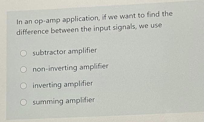
Find explanation below
Step by step
Solved in 2 steps
- Design of op amp circuit Find the value ofC2. ( need handwritten only ,otherwise downvote.)For the circuit shown above, find an expression between the inputs, v1, v2, v3 and v4 and vO. Make simplifying assumptions about the OP-AMP such as v+=v- but you must state the conditions for which this assumption is correct. As soon as possible!Use two ideal op amps to implement the function: Vo= V1+2V2-3V3.
- Assume that the op amp in the circuit shown is ideal. How large can Rx be before the amplifier saturates?ex: also could you help explain if consider this as an op-amp circuit, why the 1k ohms resistance belongs inside the amplifier but not Rin?For the circuit shown above, find the gain (vo / vi). Make simplifying assumptions about the OP-AMP such as v+= v- but you must state the conditions for which this is true. Please as soon as possible!
- a) Design a non-inverting amplifier using an ideal op amp that has a gain 7.5.b) If you wish to amplify signals between -2V and 1.2V using the circuit you designed in part (a) what arethe smallest power supply voltages you can use?c) Draw your final circuit diagram.d) Assume that the voltage signal source is vs = −1V and the feedback resistor Rf is replaced with avariable resistor. Specify the range of Rf (in kΩ ) which will cause the op amp to saturate?Assume that the ideal op amp in the circuit seen is operating in its linear region, Show that vo=[(R1+R2)/R1]vs.Please show that gain = -(1-n)/(1+nA) , n = R1/(R1+R2) and compare to gain of ideal op amp. Calculate the input and output impedances, and lastly whats the point of the resistor R1//R2 on the non-inverting input? What would be the best value for this resistor? (pretending it wasn't given that the value is R1/R2).