In the circuit shown in figure beside, (i=5+20sin1000t+ 10sin2000t+5sin3000t) Amp. Wnte the non-sinusoidal curent equation in each branch then find the total dissipated power in the circuit 1300 102
In the circuit shown in figure beside, (i=5+20sin1000t+ 10sin2000t+5sin3000t) Amp. Wnte the non-sinusoidal curent equation in each branch then find the total dissipated power in the circuit 1300 102

Power System Analysis and Design (MindTap Course List)
6th Edition
ISBN:9781305632134
Author:J. Duncan Glover, Thomas Overbye, Mulukutla S. Sarma
Publisher:J. Duncan Glover, Thomas Overbye, Mulukutla S. Sarma
Chapter2: Fundamentals
Section: Chapter Questions
Problem 2.7P: Let a 100V sinusoidal source be connected to a series combination of a 3 resistor, an 8 inductor,...

Related questions
Question
Solve this ...with me time 35 minutes
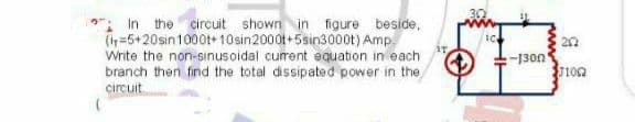
Transcribed Image Text:: In the circuit shown in figure beside,
(in=5+20sin1000t+10sin2000t+5sin300ot) Amp.
Write the non-sinusoidal current equation in each
branch then find the total dissipated power in the
circuit
-1300
102
Expert Solution
This question has been solved!
Explore an expertly crafted, step-by-step solution for a thorough understanding of key concepts.

Step by step
Solved in 2 steps with 2 images

Knowledge Booster


Learn more about
Need a deep-dive on the concept behind this application? Look no further. Learn more about this topic, electrical-engineering and related others by exploring similar questions and additional content below.Recommended textbooks for you
Power System Analysis and Design (MindTap Course …
Electrical Engineering
ISBN:
9781305632134
Author:
J. Duncan Glover, Thomas Overbye, Mulukutla S. Sarma
Publisher:
Cengage Learning
Power System Analysis and Design (MindTap Course …
Electrical Engineering
ISBN:
9781305632134
Author:
J. Duncan Glover, Thomas Overbye, Mulukutla S. Sarma
Publisher:
Cengage Learning