Key =93 Consider the circuit shown below. Here, R = 2092, R2 = 1092, ZL = +jKEYN and Zc = -j102. The phasor current source is I, = 100e/60° A at 50 Hz. 1. For what load impedance ZLOAD will maximum power be transferred to the load? 2. What will be the maximum power transferred to the load? 3. What is the power factor of the source under the conditions of maximum power transfer? Zc ZL Is R1 ZLOAD
Key =93 Consider the circuit shown below. Here, R = 2092, R2 = 1092, ZL = +jKEYN and Zc = -j102. The phasor current source is I, = 100e/60° A at 50 Hz. 1. For what load impedance ZLOAD will maximum power be transferred to the load? 2. What will be the maximum power transferred to the load? 3. What is the power factor of the source under the conditions of maximum power transfer? Zc ZL Is R1 ZLOAD

Power System Analysis and Design (MindTap Course List)
6th Edition
ISBN:9781305632134
Author:J. Duncan Glover, Thomas Overbye, Mulukutla S. Sarma
Publisher:J. Duncan Glover, Thomas Overbye, Mulukutla S. Sarma
Chapter2: Fundamentals
Section: Chapter Questions
Problem 2.18P: Let a series RLC network be connected to a source voltage V, drawing a current I. (a) In terms of...

Related questions
Question
answer quickly
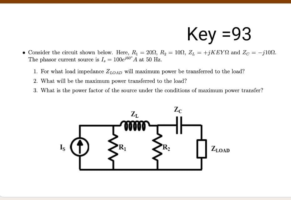
Transcribed Image Text:Key =93
102, Z, = +jKEYN and Zg = -j100.
Consider the circuit shown below. Here, R1 = 202, R2
The phasor current source is I, = 100e160° A at 50 Hz.
%3D
1. For what load impedance ZLOAD will maximum power be transferred to the load?
2. What will be the maximum power transferred to the load?
3. What is the power factor of the source under the conditions of maximum power transfer?
Zc
ZL
Is
R1
R2
ZLOAD
Expert Solution
This question has been solved!
Explore an expertly crafted, step-by-step solution for a thorough understanding of key concepts.

This is a popular solution!

Trending now
This is a popular solution!

Step by step
Solved in 5 steps with 5 images

Recommended textbooks for you
Power System Analysis and Design (MindTap Course …
Electrical Engineering
ISBN:
9781305632134
Author:
J. Duncan Glover, Thomas Overbye, Mulukutla S. Sarma
Publisher:
Cengage Learning
Power System Analysis and Design (MindTap Course …
Electrical Engineering
ISBN:
9781305632134
Author:
J. Duncan Glover, Thomas Overbye, Mulukutla S. Sarma
Publisher:
Cengage Learning