iz R2 R i = 0 Figure 1.20 Inverting amplifier using op amp.
Q: For the Op-Amp circuit shown below, v1(t) = 0.02 sin 200t V and v2(t) = 0.03 sin 200t V. Determine…
A: For the op-amplifier circuit shown below calculation of output voltage: v1t=0.02sin200t…
Q: L. Design a suitable op amp circuit to implement the following equation: 1 = 20V, – sv, ) + 6 fv, -…
A: Since you have asked multiple questions, we will solve the first question for you. If you want any…
Q: Figura 8. R1 = 2kN, R2 = 10kN, R3 = 4kN, R4 = 6kN %3D %3D %3D
A:
Q: The op amp in the circuit shown is ideal. Find io (in microamperes) when σ=0.272.
A: Find the Thevenin equivalent of the following circuit.
Q: 5. For the multistage op amp circuit shown, find the output voltages vo1, Vo2, Vo3, and vo4, and the…
A:
Q: 3. For the op-amp circuit below, determine the expression for the output voltage. Be sure to show…
A: Here to find the output voltage of opamp principle of super position was used.fist one source acting…
Q: R4 R3 OA1 Vo R2 R1 + Vin RL VL Write node-voltage equations: one for each input terminal of the op…
A: Use virtual ground concept.
Q: For the op amp circuit shown in the Figure, if Vs= 11 mV, Ry 10 KO, R1-8 KO and R2-1 KO, the value…
A:
Q: R1 R1 R1 V20 R1
A: To prove the output of final opamp is Vo = (R0/R1)*(V2 - V1) Use virtual ground concept of opamp and…
Q: Problem 2 Cascaded Op Amp System Assume ideal operational amplifiers therefore you can use summing…
A:
Q: What is the summing amplifier output voltage vo as shown if v1 =2 sin 1000πt V, v2 = 4 sin 2000πt V,…
A: Given: A summing amplifier in which
Q: For the circuit shown, • Rz = 1 k2 • R2= 15 kQ R, R, R4 • R3 = 1 k2 R, R4 = 1.5 ko Rg. • Rg = 4.7 kN…
A:
Q: Design an Op-Amp circuit to represent the following differential equation: 2V,4) +10“Y10)+4V,t)=0 dt
A: Solution: Differential equation. 2Vot+10dV1tdt+4V2t=0Vot=-5dV1tdt-2V2tClearly output is the sum of…
Q: Consider the op amp circuit given below, where R = 19 kQ and vs = 1 V. NOTE: This is a multi-part…
A: The output voltage of the given circuit is determined as shown below
Q: A certain microphone is capable of delivering 0.5 V when someone claps their hands at a distance of…
A: Given:Ith=100 mARth=620ΩVin=0.5V
Q: The op amp in the circuit shown is ideal. What op amp circuit configuration is this?
A: The Op Amp can be classified based on the input given to the terminal as: Inverting Op amp…
Q: For the Op Amp circuit, write the equation for Vo in terms of V1 and V2: V. OUT OPAMP R1 1k V1 R2 R3…
A:
Q: Figure Q. 3(b) shows an op amp circuit for linear amplifier application. (i) Determine the value of…
A:
Q: The op amp circuit of the figure shown below will remove the DC portion of the input voltage, v1(t),…
A: Using the virtual ground concept, the voltage at the inverting terminal is equal to the voltage at…
Q: Design a combinational circuit with three inputs (E,L,Y) and three outputs (F,R,A). If the input is…
A: As per company guidelines, we are supposed to answer the first 3 subparts of the question. Kindly…
Q: 2) The op amp in the circuit that shown in next figure is ideal and ±15 V is used as power supplies…
A: Given an op amp circuit shown
Q: Draw equivalent circuit and derive the voltage gain A,- VN1=-(R/R1)/[1+(1+R>/R1)/A»] for an…
A: Given that Prove that Av=(-R2R1)(11+1+R2R1A)
Q: Q2: Calculate the output voltage Vo for the op amp circuit shown in Figure below. 18 V 1.6 k www 7.5…
A: We need to find out the output voltage for given circuit
Q: a) As an electronic engineer, you are given a project to design a circuit using operational…
A:
Q: totype AI robot for industry that will be supplied by a 12V dc. This AI robot as they envision has a…
A: Solution- The model can be designed as- From the question, load resistance will be varies as 250…
Q: Draw and design two op-amp circuits that can implement the following functions: 1) Y= V₁ -²/V₂. 2)…
A: The required circuit can be designed with the help of differential amplifier and inverting amplifier…
Q: I. Design a suitable op amp circuit to implement the following equation: f = 6(2V, - 4V,)- 3 V + 2-…
A:
Q: - Vo + R R-Ar R opamp R R V1 R R V R - Vs + vo Find the expression for the gain, = f(R, Ar), using…
A:
Q: Solve
A: Redrawing the given circuit, by marking the inverting and the non-inverting terminal voltages as…
Q: 5.33.1 For the circuit involving an ideal op amp shown in the image below, if R1 = 21 k2, R2 = 24…
A:
Q: 8. Find the voltage Vx, the output voltage, Vo, and the output current, I in the circuit shown below…
A:
Q: 4.9 The supply voltage of the op amp in the circuit of Fig. P4 is 16 V. If Rµ = 3 k2, assign a…
A: As per our guidelines we are supposed to do the 1st question only. So kindly post remaining…
Q: Given the input for the circuit below draw the output waveform in the graph sheet endlosed herewith.…
A: Given DataR1 = 10 K ohms R2 = 5 K ohms R3 = 10 K ohms Rf = 20 K ohms
Q: Consider the op amp circult below. You can assume the ampliffer is Ideal. ic R Vout a) If vin = 3 V…
A: The op-amp circuit is shown below, Assuming that the operational amplifier is ideal. We can see…
Q: # Implement the following function using Op Amps: O E = 11 - 11 V2 + 10 d Vs dt (ii) F2 = 11Vy – 15…
A: We need to implement the following given function using Op-amps: i F1=11v1-11v2+10dv3dt,ii…
Q: Q2: (a) Design an operational-amplifier circuit that will produce an output equal to -(4v₁ + V₂ +…
A: The solution is provided in the following section.
Q: In the circuit shown below, if R1=R2=R3=R4, then the voltage at the negative terminal of the Op-amp…
A:
Q: Find i, in the op amp circuit shown, 50 k2 +. 10 k2 0.4 V 20 k2 +) ww
A: In this question we will find output current of opamp..
Q: Q2 i) Find DTFT of a) X[n]= δ[n+5] -αn δ[n-5] b) X[n]=(n-1) (1/3)n u[n] please solve step by step…
A:
Q: VIN3 =2 V R3; Rf=2*R1; VINI = 0.2 V; VIN2= 1 V and (b) Find the output voltage value when R1 =R2 =D…
A:
Q: R + R R R-Ar R vo Find the expression for the gain, = f(R, Ar), using an ideal op amp model. vs
A:
Q: For the circuit above, R= 4MΩ and C = 0.75μF. Vi(t)= −t^2V for 0s≤t≤5s. What is the value of Vo at…
A: In this question , we will find output of opamp..
Q: a) Sketch Vo versus time for the circuit shown with the input given. b) Determine DC output voltage…
A: The solution can be achieved as follows.
Q: You are given the following circuit. Assume that V1 = 5.4 V, V2 = 5.8 V, V3 = 5.2 v, V4 = 4.5 V, V5…
A: In this question, We need to determine the Voltage Vn ? We are solving this problem using the…
Q: An instrumentation amplifier is used when the application signal is very low. For the circuit shown…
A: Since there are 2 different questions, as per the guidelines, the following section (d) will be…
Q: The obtained total power dissipation is too high for a specific application. Design a circuit, by…
A: Power is the time rate of change of energy. Its SI unit is watt. Formula to calculate power is given…
Q: v(t) R₁ Μ 10 ΚΩ Vm sin(at) R₂ 100 ΚΩ + θα RL
A:
Q: 1. Consider the ideal op-amp circuit below. Let Us = 0.1 V, R1 = R2 = R3 = Rz = 100 k2, and R4 = 98…
A: We know that for an ideal Op-amp the potential of inverting and non inverting terminal are same. The…
Q: Example:. Find A (ct)? 10 B 2 www.li A Op-amp www 7 V₂
A:
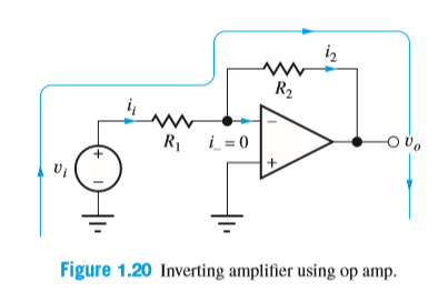
Write an expression for the output voltage vo(t) of the circuit shown if R1 =910Ω,R2 =7.5kΩ, and vi(t) = (0.01sin750πt) V. Write an expression for the current is(t).
Trending now
This is a popular solution!
Step by step
Solved in 3 steps with 3 images
- 3ZD Calculate the output voltage of an op-amp if a 100mV signal is applied to the non-inverting input of the op-amp circuit which has an Rf = 0 Ohms and Ri = 0 Ohms. a.Infinity Volts b.0 Volts c.1 Volts d.-2 VoltsHi!! I need answer, ASAP. Thank you! Calculate the output impedance of an inverting op-amp using the 741 op-amp (ro =100 Ohms, AOL =200,000) if Ri = 33 kilo Ohms and Rf = 77 kilo Ohms.Calculate ix and v0 in the circuit attached. Assume that the output of the Op-Amp is constrained to lie between -15V and 15V.
- In Basic electronics lab on summing amplifier Arifa is asked to give the circuit connectionaccording to figure below to make a three input summing amplifier. She uses IC 741 as OP-AMPand two power supplies to power up the IC. According to the instruction of his teacher she usesthree input such that ?1 = 2?, ?3 = −1? & set ?2 such that the output voltage ?0 = −16.5?. A. What is the virtual ground of OP-AMP?B. Draw the equivalent circuit of OP-AMP and then simplify it for Ideal case.C. Determine the value of ?2 from the figure above for which ?0 = −16.5?.D. If the 50KΩ feedback resistor is replaced by a capacitor of 100uF what will be the outputvoltage after 1 second. Use the value of ?2 = 5 ???(200??)?�Calculate the voltage of an inverting op-amp summing amplifier for the following sets of resistors. Use Rf = 1 MΩ in all casesa) V1 = 1V, V2 = 2V, V3 = 3V, R1 = 500 kΩ, R2 = 1MΩ, R3 = 1 MΩb) V1 = -2V, V2 = 3V, V3 = 1V, R1 = 200 kΩ, R2 = 500 kΩ, R3 = 1 MΩSketch the circuit of summing amplifier using op amp to get Vout= 2V1+ 3V2+5V3.
- Determine the output voltage of an op amp amplifier circuit with the following parameters: Differential voltage gain = 4522CMRR = 631Vi1 = 659 mV Vi2 = 659 mV Vi1 and Vi2 are in phase and have the same frequency. \ QUICKLYSolve the summing amplifier for V0, assuming it is an ideal opampDetermine v0 and i0 in the Cascaded Op-Amp circuit below
- Q1. Assume that Op-Amp as shown above is ideal. Given that R1 is 0.29 Ohm, R2 is 1.7 Ohm, R3 is 2.03 Ohm, R4 is 2.125 Ohm. Calculate Vo, V2 & I3.Calculate the output voltage of an op-amp summing amplifier for the given values of voltages and resistors. Use Rf = 1 MΩ. V1 = 5.84V V2 = 8.47V V3 = 8.25V R1 = 482kΩ R2 = 0.58MΩ R3 = 1.31MΩ QUICKLY3S Which of the followinh statements are true about an op-amp? a.op-amps have very high input impedance b.all of the statements c.op-amps have very low output impedance d.op-amps are very high gain DC amplifiers