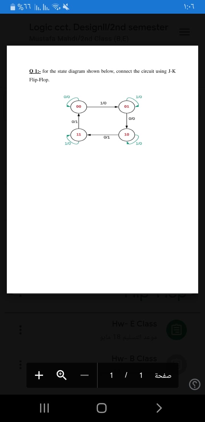
O 1:- for the state diagram shown below, connect the circuit using J-K Flip-Flop. 0/0 1/0 1/0 00 01 0/0 0/1 11 10 0/1 1/0 1/0


Q: Analyze the following circuit diagram and the truth table and answer the following question: Master…
A: c) Master Slave JK flip flop implementation:- The Master-Slave Flip-Flop is basically a combination…
Q: Design a Moore State Machine that implements the State Diagram using D Flip-Flops. What are the…
A: Using D flip-flops and NAND gates, design a Moore finite state machine with one input x and one…
Q: By using a S-R flip - flop design a binary counter with the following sequence 0, 1, 2,3,5,4,7,0
A:
Q: Draw a circuit diagram of 4 bit full adder and full subtractor.
A: Screenshot of 4-bit Full Adder and full subtractor:
Q: State diagram given for a sequential circuit with 3 flip-flops A,B,C and 1 input X and 1 output Y.…
A: Step 1:- Given:-
Q: By using a S-R flip - flop design a binary counter with the following sequence 0, 2, 4 ,7,6,5,3,…
A:
Q: What is the minimum number of D flip-flops required to design a counter circuit that outputs the…
A: A D flip-flop is a digital electronic circuit used to delay the change of state of its output signal…
Q: For the circuit shown below, determine the Boolean functions at point X and Y as well as the output…
A: Please check the step 2 for solution
Q: The difference between a combinational circuit and a flip flop is: O a. The flip flop needs a next…
A: Answer: Option d Flip flops requires a clock pulse
Q: A sequential circuit counts from 0 to 255 using JK flip-flop. If the propagation delay of each flip…
A: The above question is solved in step 2 :-
Q: Using MUX, design a circuit that has the following min-term: F = E(A.B,C,D) (1,3,4,11,12,13,14,15),…
A:
Q: The following figure shows a sequential circuit with one D Flip Flop with a common input clock (C).…
A: Actually, flip-flop is nothing but a circuit.
Q: Draw the the state transition diagram for a sequential circuit with one JK flip-flop, FFA; one T…
A: The complete answer is given below .
Q: 2- Design Asynchronous counter using positive edge J-K flip flop to count the following states…
A: Given that Design a Asynchronous counter using positive edge J-K flipflop to count the following…
Q: In the sequential circuit; The current state of a two JK flip-flop is QA =0, QB=0. and a clock is…
A: QA=1 and QB=1
Q: Design a binary counter that counts from 0 to 5. At each clock pulse, 3 lights will be ON and 3…
A: state table:
Q: Design an Octal Counter with D flip-flops. a) Draw the state diagram b) Draw the state table c) Draw…
A:
Q: 2. An X-Y flip flop, whose characteristic table is given below is to be implemented using a J-K flip…
A: We are given a XY flip flop whose characteristic table is also given, we are going to write…
Q: Design the sequential circuit specified by the state diagram in the figure below, using JK…
A:
Q: Design a circuit that will function as prescribed by the state diagram shown in Figure 13.38. Use…
A: Question :-
Q: Design and Simulate Master Slave flip flop using IC’s.
A: Design and Simulate Master Slave flip flop using IC’s.
Q: 3. A new flip flop with 2 input A & B is designed using the JK flip flop. The characteristic table…
A: Here in this question we have given a new flip flop with two Input A and B which is designed using…
Q: Design a sequential circuit that can recognize the sequence 1010 using JK flip flop. You haveto find…
A: Lets see the solution.
Q: Design a circuit that will function as prescribed by the state diagram shown in Figure 13.38. Use…
A: Question :-
Q: Design a 4bit Up/Down counter using JK-flip flop (7476). Construct logical circuit which decodes all…
A: The above two counters can be implemented in a single counter called up down counter.This can be…
Q: For the initial state of 000, the function performed by the arrangement of the J-K flip-flop in the…
A: Shift register counters are a series of a sure quantity of center registers which can be related…
Q: A sequential circuit has one flip-flop Q, two inputs x and y, and one output S. It consists of a…
A: The Full adder equation will be: S = X ⊕Y ⊕ QC = XY + XQ + YQ The input equations will be: DQ = C…
Q: 1. In the shown digital circuit F is equal to: а. 0 b. 1 c. x +y d. None of the above y So 4 x I MUX…
A:
Q: The Following is a state diagram for a self correcting 4 bit ring counter, what is the illigal…
A: A counter is called as self correcting ring counter if it is possible to enter counter loop…
Q: Design a MOD-10 4-bit downward ripple counter using D Flip Flop having asynchronous RESET. Show the…
A: The above question is solved in step 2:-
Q: AA SO/- start 1 $1/- M[0] add 52/ shift, CU CD 1 CU-count up $3/done
A: Total answers posted by the expert is: 19 Only one flip-flop is in active state or "1" at a time…
Q: Use T flip flops to design a counter with the repeated binary sequence: 0,1,3,5,7. The circuit is to…
A: Although for T flip flop excitation table is given by The state diagram of the given binary…
Q: Q 1:- for the state diagram shown below, connect the circuit using J-K Flip-Flop. 0/0 1/0 1/0 00 01…
A: The values in the state diagram can be represented as a truth table. The values in the circle…
Q: The next state table of a 2-bit saturating up- counter is given below. Q1 Q0 Qi 2 1 1 1 1 1 1 1 1…
A: The answer given as below:·
Q: The following state diagram represents 00 01 ܣܪܣ Select one: OT flip-flop O SR flip-flop OD…
A: The flip flop is an electronic circuit with the two stable states which can be used to store the…
Q: Consider the following circuit involving three D-type flip-flops as shown in the figure below. If at…
A: D flip-flop : The D flip-flop is an edge triggered device which transfers input data to Q on clock…
Q: To 0 X 19₁9₁=00 X Q.Q=01 X Q₁Q=11 K Z
A: Here i am using jk flip flop for each state: explanation…
Q: It is required to design a 3-bit counter using T flip flop. The output sequence is: 000, 010, 100,…
A: Here solve one by one: ========================================================================…
Q: The minimum number of JK flip-flop required to construct a synchronous counter with the count…
A: minimum number of flip flops required for the sequences of count is in step 2.
Q: Consider the following sequential circuit. Determine its state table and state diagram. Cp K 10
A: Given sequential circuit contains 2 J-K flip flops and there is one input. First flip flop's output…
Q: Figure 2 shows a state diagram of a binary counter up and down in decimal number. By using D flip…
A: Question: - Derive the simplified Boolean expression for each flip flop using K-maps. Please take…
Q: 2- Design Asynchronous counter using positive edge J-K flip flop to count the following states…
A: answer 2 Given that Design a Asynchronous counter using positive edge J-K flipflop to count the…
Q: erive State Table and Draw State Diagram of the iven clocked sequential Circuit Clk K B Clk Dt K
A:
Q: A circuit's transition diagram is given in the Figure 1; a. Design the circuit with binary state…
A: The complete answer is given below.
Q: Problem 5: Explain why the circuit in Figure 4 is a 4-to-1 MUX. 注D Vo V1 f W2 En Figure 4
A: According to the information given:- We have to explain why the circuit is a 4 to 1 MUX.
Q: Fill in the timing diagram for a falling-edge-triggered S-R flip-flop. Assume Q begins at 0. L Clock…
A: We need to find the timing diagram of falling edge triggered SR flip flop.
Q: Q.6 For the circuit in Figure 02 , assume the inputs are Add/Subt. = 1, A =1010, and B = 1101. What…
A: Note: Answering the first question as per the guidelines. From figure 2, it can be observed that…
Q: Design a counter with the following repeated binary sequence: 0, 1, 2, 4, 6. Use S-R flip-flops.…
A:
Q: Q6) Design a counter with JK flip-flops that counts primary numbers (2,3,5,7,11,13) in loop, show…
A: Design a counter with JK flip-flops that counts primary numbers(2,3,5,7,11,13) in loop,show the…


Trending now
This is a popular solution!

Step by step
Solved in 3 steps with 5 images


- I need explenation Consider the circuit above where the combinational circuit is represented by comb and clock skew is represented by tskew. Given the following parameters: Flip-Flop hold time = 2 ns Flip-Flop setup time = 10 ns Flip-Flop propagation delay = 12 to 20 ns Tcomb 1 ➔ 5 ns to 7 ns Tcomb 2 ➔ 6 ns to 11 nsIdentify the state diagram operation and find its output sequence for the following input sequence X=0101-1100-101-0000 the circuit accepts input bits from LSB to MSBDraw the circuit diagram for the 4-bit Asynchronous Down-Counter using JK flip-flops in the space below. (Hint) Connect VCC to CLRN and a rocker switch to PRN.
- F =A'BC'+A'CD'+ACD+AB'C'D' Draw the Logic Gates diagram please Need AsapDesign a cascade of Ripple counters to count 0000, 0001, 0010, 0011, 0100, 0101, 0110, 0111, 1000, 1001, 0000, 0001, 0010, etc using T- flip flops. (ii) Explain how propagation delays affect the performance of Ripple countersGiven a 100-MHz clock signal, construct a circuit using T flip-flops to generate 50-MHz and 25-MHz clock signals.
- Draw SR Flip-flop using NAND gate and illustrate its truth table? And briefly disucss the major differences between SR-flip-flop, D-Flip-flop and JK-flip-flops? Answer should be more detailed asmuch as possibleDraw 8 bit counter using JK or D flip flop in multisim, also provide circuit diagram of it., and verify truth table also.Using suitable circuit diagrams, implement the following logic equations using CMOS i. f(xy) = overline (x + y) ii. f(xy) =( x -y) iii. f(x.y,z)=( overline x.y.z )
- The counting sequence of a 3-bit synchronous counter using JK flip-flops is as follows: 3, 5, 2, 7, 1, 4, 3Implement the counter using JK flip-flops.Design a binary counter that counts from 0 to 5. At each clock pulse, 3 lights will be ON and 3 lights will be OFF. Use JK flip flops. Steps for solution: State diagram State table K-map reductions designDraw Karnaugh synchronous counter that counts the digits 1 8 0 5 6 2 4 Design the maps with the method and draw the circuit diagram using JK flip-flops belonging to the counter Find the truth table fro all