O A) A rectifiers shown in fig.3. If the output current assumed to be ripple free. (a) Draw the output voltage and current through each SCR, for thyristor firing angle a = (45°& 75°) (b) Determine the average value of the output voltage and current if the line voltage is Vms = 400 V and R= 100 ohms when a 30°, a = 90°, and a = 135°. (c) How is the average load voltage affected if thyristor T2 failed to open circuit? %3D %3D %3D %3D
O A) A rectifiers shown in fig.3. If the output current assumed to be ripple free. (a) Draw the output voltage and current through each SCR, for thyristor firing angle a = (45°& 75°) (b) Determine the average value of the output voltage and current if the line voltage is Vms = 400 V and R= 100 ohms when a 30°, a = 90°, and a = 135°. (c) How is the average load voltage affected if thyristor T2 failed to open circuit? %3D %3D %3D %3D

Introductory Circuit Analysis (13th Edition)
13th Edition
ISBN:9780133923605
Author:Robert L. Boylestad
Publisher:Robert L. Boylestad
Chapter1: Introduction
Section: Chapter Questions
Problem 1P: Visit your local library (at school or home) and describe the extent to which it provides literature...

Related questions
Question
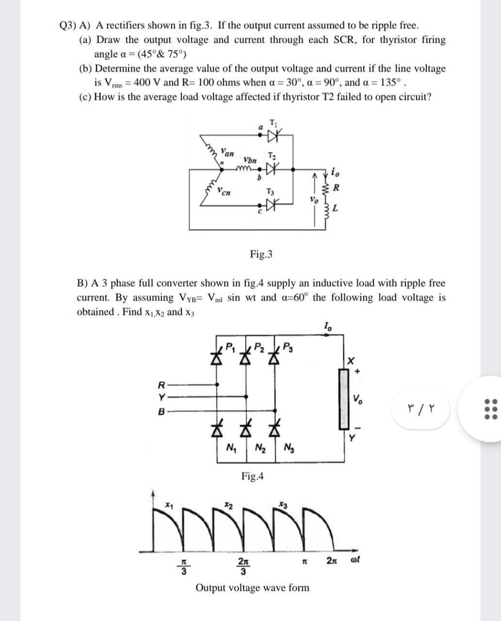
Transcribed Image Text:Q3) A) A rectifiers shown in fig.3. If the output current assumed to be ripple free.
(a) Draw the output voltage and current through each SCR, for thyristor firing
angle a = (45°& 75°)
(b) Determine the average value of the output voltage and current if the line voltage
is Vms = 400 V and R= 100 ohms when a = 30°, a = 90°, and a = 135°.
(c) How is the average load voltage affected if thyristor T2 failed to open circuit?
a
Van
T2
Vbn
io
Vcn
T3
Vo
Fig.3
B) A 3 phase full converter shown in fig.4 supply an inductive load with ripple free
current. By assuming VyB= Vml sin wt and a360° the following load voltage is
obtained . Find x1,X2 and x3
P1
P2
P3
R
Y
Vo
B
N2
Ng
Fig.4
X2
X3
2n
2n
ot
Output voltage wave form
...
Expert Solution
This question has been solved!
Explore an expertly crafted, step-by-step solution for a thorough understanding of key concepts.

Step by step
Solved in 6 steps with 8 images

Knowledge Booster


Learn more about
Need a deep-dive on the concept behind this application? Look no further. Learn more about this topic, electrical-engineering and related others by exploring similar questions and additional content below.Recommended textbooks for you
Introductory Circuit Analysis (13th Edition)
Electrical Engineering
ISBN:
9780133923605
Author:
Robert L. Boylestad
Publisher:
PEARSON

Delmar's Standard Textbook Of Electricity
Electrical Engineering
ISBN:
9781337900348
Author:
Stephen L. Herman
Publisher:
Cengage Learning

Programmable Logic Controllers
Electrical Engineering
ISBN:
9780073373843
Author:
Frank D. Petruzella
Publisher:
McGraw-Hill Education
Introductory Circuit Analysis (13th Edition)
Electrical Engineering
ISBN:
9780133923605
Author:
Robert L. Boylestad
Publisher:
PEARSON
Delmar's Standard Textbook Of Electricity
Electrical Engineering
ISBN:
9781337900348
Author:
Stephen L. Herman
Publisher:
Cengage Learning
Programmable Logic Controllers
Electrical Engineering
ISBN:
9780073373843
Author:
Frank D. Petruzella
Publisher:
McGraw-Hill Education

Fundamentals of Electric Circuits
Electrical Engineering
ISBN:
9780078028229
Author:
Charles K Alexander, Matthew Sadiku
Publisher:
McGraw-Hill Education

Electric Circuits. (11th Edition)
Electrical Engineering
ISBN:
9780134746968
Author:
James W. Nilsson, Susan Riedel
Publisher:
PEARSON

Engineering Electromagnetics
Electrical Engineering
ISBN:
9780078028151
Author:
Hayt, William H. (william Hart), Jr, BUCK, John A.
Publisher:
Mcgraw-hill Education,