ural tensile stress in the bea stress at a section I m from section. ural compression stress in t ural compression stress at = and compressive stress
ural tensile stress in the bea stress at a section I m from section. ural compression stress in t ural compression stress at = and compressive stress

Mechanics of Materials (MindTap Course List)
9th Edition
ISBN:9781337093347
Author:Barry J. Goodno, James M. Gere
Publisher:Barry J. Goodno, James M. Gere
Chapter9: Deflections Of Beams
Section: Chapter Questions
Problem 9.4.7P: -7 A beam on simple supports is subjected to a parabolically distributed load of intensity q(x) =...

Related questions

Question
Transcribed Image Text:3 36 ull Eull KOREK TELECOM
Asiacell
20212pdf.pdf →
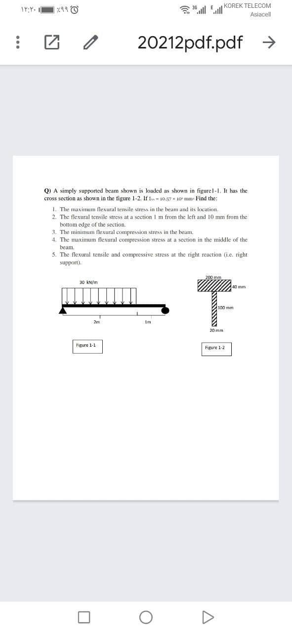
Q) A simply supported beam shown is loaded as shown in figurel-I. It has the
cross section as shown in the figure 1-2. If Is = 10.57 x 10 mm- Find the:
1. The maximum flexural tensile stress in the beam and its location.
2. The flexural tensile stress at a section I m from the left and 10 mm from the
bottom edge of the section.
3. The minimum flexural compression stress in the beam.
4. The maxinum flexural compression stress at a section in the middle of the
beam.
5. The flexural tensile and compressive stress at the right reaction (i.c. right
support).
30 kN/m
40 mm
2m
Figure 1-1
Figure 1-2
Expert Solution
This question has been solved!
Explore an expertly crafted, step-by-step solution for a thorough understanding of key concepts.

Step by step
Solved in 3 steps with 3 images

Knowledge Booster


Learn more about
Need a deep-dive on the concept behind this application? Look no further. Learn more about this topic, mechanical-engineering and related others by exploring similar questions and additional content below.Recommended textbooks for you
Mechanics of Materials (MindTap Course List)
Mechanical Engineering
ISBN:
9781337093347
Author:
Barry J. Goodno, James M. Gere
Publisher:
Cengage Learning
Mechanics of Materials (MindTap Course List)
Mechanical Engineering
ISBN:
9781337093347
Author:
Barry J. Goodno, James M. Gere
Publisher:
Cengage Learning