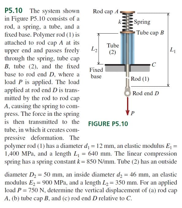
P5.10 The system shown in Figure P5.10 consists of a rod, a spring, a tube, and a fixed base. Polymer rod (1) is attached to rod cap A at its upper end and passes freely through the spring, tube cap B, tube (2), and the fixed base to rod end D, where a load P is applied. The load applied at rod end D is trans- mitted by the rod to rod cap A, causing the spring to com- press. The force in the spring is then transmitted to the FIGURE P5.10 tube, in which it creates com- Rod cap A L₂ Fixed base k Tube (2) Spring Tube cap B Rod (1) C Rod end D P L₁ pressive deformation. The polymer rod (1) has a diameter d₁ = 12 mm, an elastic modulus E₁ = 1,400 MPa, and a length L₁ = 640 mm. The linear compression spring has a spring constant k = 850 N/mm. Tube (2) has an outside diameter D₂ = 50 mm, an inside diameter d₂ = 46 mm, an elastic modulus E₂ = 900 MPa, and a length L₂ = 350 mm. For an applied load P = 750 N, determine the vertical displacement of (a) rod cap A, (b) tube cap B, and (c) rod end D relative to C.


The system shown
in Figure P5.10 consists of a
rod, a spring, a tube, and a
fixed base. Polymer rod (1) is
attached to rod cap A at its
upper end and passes freely
through the spring, tube cap
B, tube (2), and the fixed
base to rod end D, where a
load P is applied. The load
applied at rod end D is transmitted
by the rod to rod cap
A, causing the spring to compress.
The force in the spring
is then transmitted to the
tube, in which it creates compressive
deformation. The
polymer rod (1) has a diameter d1 = 12 mm, an elastic modulus E1 =
1,400 MPa, and a length L1 = 640 mm. The linear compression
spring has a spring constant k = 850 N/mm. Tube (2) has an outside diameter D2 = 50 mm, an inside diameter d2 = 46 mm, an elastic
modulus E2 = 900 MPa, and a length L2 = 350 mm. For an applied
load P = 750 N, determine the vertical displacement of (a) rod cap
A, (b) tube cap B, and (c) rod end D relative to C.


Trending now
This is a popular solution!

Step by step
Solved in 3 steps


