Prob. 4.5-10. The steel shaft AD in Fig. P4.5-4 (G = 80 C is subjected to torsional loads at sections B and D, as sh in the figure. The diameters are: d = d2 = 40 mm., and 30 mm. (a) Determine the value of the torque Tp adde D that would make the rotation at C equal to zero, th: %3D %3D
Prob. 4.5-10. The steel shaft AD in Fig. P4.5-4 (G = 80 C is subjected to torsional loads at sections B and D, as sh in the figure. The diameters are: d = d2 = 40 mm., and 30 mm. (a) Determine the value of the torque Tp adde D that would make the rotation at C equal to zero, th: %3D %3D

Mechanics of Materials (MindTap Course List)
9th Edition
ISBN:9781337093347
Author:Barry J. Goodno, James M. Gere
Publisher:Barry J. Goodno, James M. Gere
Chapter3: Torsion
Section: Chapter Questions
Problem 3.5.11P: -11 A solid steel bar (G = 11.8 X 10⁶ psi ) of diameter d = 2,0 in. is subjected to torques T = 8.0...

Related questions
Topic Video
Question
Please help me
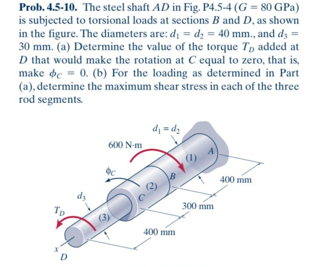
Transcribed Image Text:Prob. 4.5-10. The steel shaft AD in Fig. P4.5-4 (G = 80 GPa)
is subjected to torsional loads at sections B and D, as shown
in the figure. The diameters are: dı = d2 = 40 mm., and d3 =
30 mm. (a) Determine the value of the torque Tp added at
D that would make the rotation at C equal to zero, that is,
make oc = 0. (b) For the loading as determined in Part
(a), determine the maximum shear stress in each of the three
rod segments.
d = d,
600 N-m
(1)
B
400 mm
dz
Tp
300 mm
400 mm
D
Expert Solution
This question has been solved!
Explore an expertly crafted, step-by-step solution for a thorough understanding of key concepts.

This is a popular solution!

Trending now
This is a popular solution!

Step by step
Solved in 2 steps with 1 images

Knowledge Booster


Learn more about
Need a deep-dive on the concept behind this application? Look no further. Learn more about this topic, mechanical-engineering and related others by exploring similar questions and additional content below.Recommended textbooks for you
Mechanics of Materials (MindTap Course List)
Mechanical Engineering
ISBN:
9781337093347
Author:
Barry J. Goodno, James M. Gere
Publisher:
Cengage Learning
Mechanics of Materials (MindTap Course List)
Mechanical Engineering
ISBN:
9781337093347
Author:
Barry J. Goodno, James M. Gere
Publisher:
Cengage Learning