Problem #1: 7-4. A binary ripple counter starts from 0 and counts up to 511. (a) What is the MOD number of this counter? (b) How many J-K FFs will be required to design this counter? (c) Find the value of the FFs after 520 input pulses. (d) If the input signal has a frequency of 1024 kHz, what will the fre- quency at the MSB output?
Problem #1: 7-4. A binary ripple counter starts from 0 and counts up to 511. (a) What is the MOD number of this counter? (b) How many J-K FFs will be required to design this counter? (c) Find the value of the FFs after 520 input pulses. (d) If the input signal has a frequency of 1024 kHz, what will the fre- quency at the MSB output?

Chapter22: Sequence Control
Section: Chapter Questions
Problem 6SQ: Draw a symbol for a solid-state logic element AND.

Related questions
Question
100%
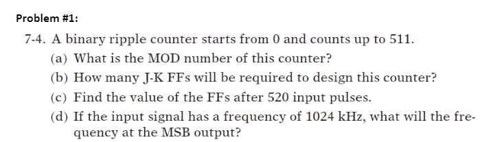
Transcribed Image Text:Problem #1:
7-4. A binary ripple counter starts from 0 and counts up to 511.
(a) What is the MOD number of this counter?
(b) How many J-K FFs will be required to design this counter?
(c) Find the value of the FFs after 520 input pulses.
(d) If the input signal has a frequency of 1024 kHz, what will the fre-
quency at the MSB output?
Expert Solution
This question has been solved!
Explore an expertly crafted, step-by-step solution for a thorough understanding of key concepts.

This is a popular solution!

Trending now
This is a popular solution!

Step by step
Solved in 2 steps

Knowledge Booster


Learn more about
Need a deep-dive on the concept behind this application? Look no further. Learn more about this topic, electrical-engineering and related others by exploring similar questions and additional content below.Recommended textbooks for you