
Introductory Circuit Analysis (13th Edition)
13th Edition
ISBN: 9780133923605
Author: Robert L. Boylestad
Publisher: PEARSON
expand_more
expand_more
format_list_bulleted
Related questions
Question
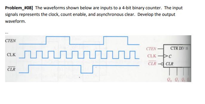

Transcribed Image Text:**Problem #08** The waveforms shown below are inputs to a 4-bit binary counter. The input signals represent the clock, count enable, and asynchronous clear. Develop the output waveform.
**Diagram Explanation:**
The diagram consists of three waveforms labeled CTEN (Count Enable), CLK (Clock), and CLR (Clear):
1. **CTEN (Count Enable):**
- The waveform is high initially, then goes low, stays low for a duration, goes high again, and repeats this pattern periodically.
2. **CLK (Clock):**
- This is a regular, square wave with a consistent frequency, cycling between high and low states.
3. **CLR (Clear):**
- The waveform begins low, transitions to high, and then returns to low, repeating periodically.
**Circuit Schematic Explanation:**
To the right of the waveforms, there is a partial schematic labeled "CTR DIV 16":
- **Inputs:**
- CTEN, CLK, CLR are connected to the counter circuit.
- **Outputs:**
- The output is labeled with Q₃, Q₂, Q₁, and Q₀, representing the bits of the binary counter.
This setup implies that the 4-bit counter produces an output that changes according to the input waveforms, with an asynchronous clear affecting the count sequence. The task is to analyze the waveform inputs to predict the resulting state changes in the counter's output.
Expert Solution
This question has been solved!
Explore an expertly crafted, step-by-step solution for a thorough understanding of key concepts.

This is a popular solution

Trending nowThis is a popular solution!

Step by stepSolved in 3 steps with 1 images

Knowledge Booster


Learn more about
Need a deep-dive on the concept behind this application? Look no further. Learn more about this topic, electrical-engineering and related others by exploring similar questions and additional content below.Similar questions
- 2. Generate 4x2 Priority encoder truth table and draw logic circuit diagram and schematic. Construct and verify if the circuit prioritizes the highest input only. (You must not use the standard priority encoder ICs included in Circuit Verse)arrow_forward7. Draw a logic diagram for a 5-bit ring counter has an initial state 01011 and determine the waveform for each Q output during 5 clock pulses.arrow_forwardneed helparrow_forward
arrow_back_ios
arrow_forward_ios
Recommended textbooks for you
- Introductory Circuit Analysis (13th Edition)Electrical EngineeringISBN:9780133923605Author:Robert L. BoylestadPublisher:PEARSON
 Delmar's Standard Textbook Of ElectricityElectrical EngineeringISBN:9781337900348Author:Stephen L. HermanPublisher:Cengage Learning
 Programmable Logic ControllersElectrical EngineeringISBN:9780073373843Author:Frank D. PetruzellaPublisher:McGraw-Hill Education
  Fundamentals of Electric CircuitsElectrical EngineeringISBN:9780078028229Author:Charles K Alexander, Matthew SadikuPublisher:McGraw-Hill Education
 Electric Circuits. (11th Edition)Electrical EngineeringISBN:9780134746968Author:James W. Nilsson, Susan RiedelPublisher:PEARSON
 Engineering ElectromagneticsElectrical EngineeringISBN:9780078028151Author:Hayt, William H. (william Hart), Jr, BUCK, John A.Publisher:Mcgraw-hill Education,
Introductory Circuit Analysis (13th Edition)
Electrical Engineering
ISBN:9780133923605
Author:Robert L. Boylestad
Publisher:PEARSON
Delmar's Standard Textbook Of Electricity
Electrical Engineering
ISBN:9781337900348
Author:Stephen L. Herman
Publisher:Cengage Learning
Programmable Logic Controllers
Electrical Engineering
ISBN:9780073373843
Author:Frank D. Petruzella
Publisher:McGraw-Hill Education
Fundamentals of Electric Circuits
Electrical Engineering
ISBN:9780078028229
Author:Charles K Alexander, Matthew Sadiku
Publisher:McGraw-Hill Education
Electric Circuits. (11th Edition)
Electrical Engineering
ISBN:9780134746968
Author:James W. Nilsson, Susan Riedel
Publisher:PEARSON
Engineering Electromagnetics
Electrical Engineering
ISBN:9780078028151
Author:Hayt, William H. (william Hart), Jr, BUCK, John A.
Publisher:Mcgraw-hill Education,