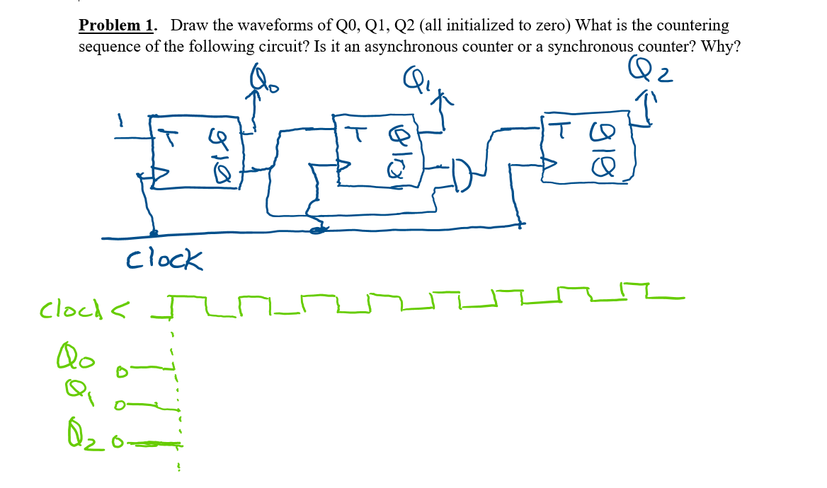
Problem 1. Draw the waveforms of Q0, Q1, Q2 (all initialized to zero) What is the countering sequence of the following circuit? Is it an asynchronous counter or a synchronous counter? Why? clock clock < J Qo


Q: Problem 2: For the circuit in Figure 2, please draw the waveforms for Qa, Qb, and Q. given the…
A: In the given circuit diagram , First flip-flop is +ve level triggered clock Second flip-flop is +ve…
Q: Design a frequency division that reduces frequency using 3 D flip flops with negative triggered edge…
A: Please give positive ratings for my efforts. Thanks. ANSWER
Q: Problem 2. Draw the output waveform of the T flip-flop for the following clock and T signals. Clock_…
A: T flip flop: In T flip flop, the input is 0 then the output is equal to previous output. If the…
Q: Consider the logic diagram and the timing diagram of the inputs X and Y graph below and answer the…
A: Timing diagrams are UML interaction diagrams used to show interactions when a primary purpose of the…
Q: Question 2 A combinational circuit is defined by the three Boolean functions below. Design the…
A:
Q: Step by step Simplify according to the rules and design before and after logic gates along with…
A: f = x'yz + xy'z + xyz' + xyz=> f = x'yz + xy'z + xyz' + xyz + xyz + xyz --OR…
Q: Design a counter using D Flip Flops and J-K Flip Flops with a rising edge clock which counts in the…
A: We have to design a 4 bit binary counter using D flip flop anr then same counter using JK flip flop…
Q: 3. a) Consider a counter circuit that contains eight JK FFs wired in the arrangement Q-Q6…
A: As per our guidelines we are allowed to answer at-most three sub-parts of a question. If you want a…
Q: Exercise 3: Consider the following sequential circuit with a clock speed of 24 KHz QA QB QC cik clk…
A: the diagram shown above is asynchronous counter using D flipflop. It uses three d flipflop so it…
Q: B) If a 10-bit ring counter has the initial state 1010000000, determine the waveform for each of the…
A: Solution: If a 10-bit ring counter has the initial state 1010000000, determine the waveform…
Q: 3. Design an asynchronous sequential circuit which has an input w and an input e. A sequence of…
A: Answer :
Q: Problem 2 Use D-type flip-flops to design a 5-bit counter (S, T, U, V, W) with the repeated binary…
A: The D flip flop is the digital electronic circuit used to delay the change of the state of its…
Q: Given the expression below, build the equivalent digital circuit NAND implementation. X = AB + CB +…
A: We have first simplified the expression to perform NAND operation in between operands then , that…
Q: Question 2: Working with Logic Gates Given the below Function: F(x, y, z) = (x + y). (y + z) + ãyz a…
A: here we have to make combinational circuits using AND,OR and NOT gate In AND gate, when allinput is…
Q: Q2: A- Here's a table showing the ten and tro for each of the components in the circuit bellow.…
A:
Q: Explain the principle of operation of the Mod-14 asynchronous counter with using the required…
A:
Q: Given the following truth table, where X, Y, and Z are input and W is output, write the canonical…
A:
Q: Design a three-bit counter like circuit controlled by the input w. Ifw = 1, then the counter adds 2…
A: Three-bit counter by using JK FLIP-FLOP is shown below:- State table:
Q: Use VHDL to implement a 16-to-1 Multiplexer. The inputs are w0, w1, w2, w3, w4, w5, w6, w7, w8, w9,…
A:
Q: öislg äbäi A synchronous state machine has two inputs (X1 and X2) and one output (Z). The…
A: The solution to the given problem is below.
Q: Assignment_5: Design a synchronous 2-bit ring counter with illegal state recovery circuitry. Analyze…
A: Ring Counter - It is built with the help of flip flop, and named as ring counter because output of…
Q: Question 2: Working with Logic Gates Given the below Function: F(x,y, z) = ( y +x).(y+z) + xyz a-…
A:
Q: Design a circuit that will function as prescribed by the state diagram shown in Figure 13.38. Use…
A: Question :-
Q: i) Propose a circuit which can sum together two 3-bit binary numbers. You can rely on notable…
A: We need to propose an adder circuit to add two 3-bit numbers.
Q: Q1) a) Design a synchronous 2-bit ring counter with illegal state recovery circuitry. Analyze the…
A: Ring Counter - It is built with the help of flip flop, and named as ring counter because output of…
Q: نقطة واحدة A synchronous state machine has two inputs (X1 and X2) and one output (Z). The…
A: The solution to the given problem is below.
Q: Problem_#03] Determine which of the logic circuits below are equivalent. D B B B (a) (b) A B. A D…
A:
Q: (a) Construct a transition table and state graph for the given circuit. (b) Construct a timing chart…
A: Answer: Consider the sequential circuit.
Q: Question 4: Given the following circuit. a b - F d a) Write the minimized form of function F (a, b,…
A:
Q: 1. O Consider the logic expression shown below F = Z + W. (X+ Y) a) Draw a transistor-level…
A: The parasitic delay of a gate is the delay of the gate when it drives zero load. It can be…
Q: 3.) Using a 3 X 8 Decoder, and 2 NAND Digital Logic Gates, and any number of Inverter Logic Gates,…
A:
Q: The following circuit shows a 3-bit ripple counter consisting of three positive edge triggered D…
A:
Q: First, you must create a logic circuit using only basic gates such as AND, OR, NOR, NAND, NOT, etc.…
A: Note: As per provided guidelines we are suppose to answer only one question at a time .please repost…
Q: 1. Draw the static CMOS circuits for the following functions. Be sure to label power, ground, and…
A: According to the information given :- We have to draw the static CMOS circuit.
Q: Suppose Q1 = 0 and Q2 = 1 is the initial state of the two flip-flop circuit shown. What is the state…
A: Solution Opt D could be the answer Detailed explanation is given below
Q: Consider the following circuit involving three D-type flip-flops as shown in the figure below. If at…
A: D flip-flop : The D flip-flop is an edge triggered device which transfers input data to Q on clock…
Q: A synchronous state machine has two inputs (X1 and X2) and one output (Z). The relationship between…
A: the asynchronous state machine has two inputs (x1 and x2) and one output (z). the relationship…
Q: Q1/ Estimate the Truth Table of the logic circuit shown below and use it to draw the timing diagram…
A: A logic gate is a basic building block of a digital circuit that has two inputs and one output.…
Q: 2- Given a BCD decade counter, show the decoding logic required to decode each of the following…
A: Actually, given information regarding BCD decade counter.
Q: Problem_#07] Develop the timing diagram for the synchronous counter shown below. HIGH 了目 Jo J2 J3 J4…
A: The Answer is
Q: Determine the output frequency for a frequency division circuit that contains 12 flip-flops with an…
A: Q. Determine the output frequency division circuit that contains 12 flip-flops with an input clock…
Q: B. Design and implement a circuit using positive edge triggered DFFS that generates a pulse (p = 1)…
A: Hey there, I am writing the required solution of the questin mentioned above. Please do find the…
Q: Suppose that Q1 = 1 and Q2 = 0 is the initial state of the two JK flip-flop circuit shown. What is…
A: The first flip-flop is connected to negative edge of clock. So when external clock goes from…
Q: TASK 2 Boolean expression: a. Given, the output X = BD+CD+ AB b. Given, the output Y = BCD+ ABD+C…
A: Solution :
Q: In the counter of Problem 4, assume that each flip-flop has a propagation delay from the triggering…
A: The counter diagram is
Q: 1- Show the design of BCD to 7- segment convertor to display (A. b.C.d. E.F.G.H. I, J) characters…
A: Answer : ans 1.
Q: Question 4: Given the following circuit. F C a) Write the minimized form of function F (a, b, c, d).…
A:
Q: 2] Design a combinational circuit with three inputs, x y, and z, and three outputs, A, B, and C.…
A: Design a combinational circuit with three inputs, x ,y , and z , and three outputs, A, B, and C .…
Q: Question 1 a) i. A synchronous counter with 4-bit, uses flip-flops with propagation delay times of…
A: (i) A four-bit synchronous counter employs flip-flops with 15-ns propagation delays. Because all the…


Trending now
This is a popular solution!

Step by step
Solved in 2 steps with 2 images


- Design a two-bit counter (sequential circuit) using falling edge triggered T-flipflops, with one input line x. When x= 1, the state of the circuit remains the same. When x = 0, the circuit goes through the state transitions byincrementing the state count, i.e., from 00 to 01, 01 to 10, 10 to 11, and 11 to 00, and repeats. Draw circuit diagramof the designed counter. if z=83,Convert z to Base-2, e.g., z= (156)10 = (10011100)2.Provide this bitstream as input to K and draw the timing diagram of the outputs of both the T-flipflops.Draw the circuit diagram for the 4-bit Asynchronous Down-Counter using JK flip-flops in the space below. (Hint) Connect VCC to CLRN and a rocker switch to PRN.Hi! I am new to logic circuits, and I am curious about this diagram. I Know that the operators are NAND operators. But I wonder what are bitwise sum and bitwise product (carry bit) at the last two outputs of the circuit. How do we compute them? For example if x1=0 and x2=1 what the output is going to be?
- Create a sequential circuit (in Logisim, preferably) which displays the integers 0 to 9 using four D-flipflops(rising-edge triggered), one GND pin, one clock input, one BCD to 7-segment LED decoder,and one 7-segment LED. The 4-bit counter must count-up.Type your question here • Design a 3-bit synchronous counter using J-K FFs only.Draw the circuit and obtain the truth table of the VHDL module below module SAM(a, b, c, M, S);input a,b,c;output M;output S;wire d,e,f;xor(S,a,b,c);and(d,~a,b);and(e,b,c);and(f,~a,c);or(M,d,e,f);endmodule
- Design and implement a minimal 5 up counter. It counts from 0 to 4 and repeats. Design the circuit such that, if the counter enters into the unwanted states: 5,6 and 7, it should jump into state 0 on the next clock pulse.Draw the schematic of a modulo-6 synchronous counter (counting sequence is 010, 110, ...). The counter has the following features: Asynchronous Reset is Active High A value R can be loaded into the counter, using the signal Load, which is Active Low.Design the simplest circuit that has three inputs, a, b, and c, which returns an output value of 1 whenever g and b are complements of each other or b and c are complements of each other, otherwise the output is 0. Realize the circuit using 4input , 3output PAL
- Design a 4-bit counter with one external input using T flip flop based on the following sequence: Input=0,6->2->9->13 (repeat), all undesired state go to 2. Input=1, 15->4->12->10 (repeat), all undesired state go to 4? *MIND TWO INPUTS THERE ARE i) State transition diagram = diag salag ii) State transition table such a example pic below iii) Simplification using 8 K-Maps required iv) circuit designIn verilog a counter must be developed from 0 to 9999 with a reset and parallel loading. The reset will be a button in charge of returning the count to 0 when pressed.For this practice, the implemented circuit will only use a 7-segment BCD converter module, which will have to be managed between the different 7-segment displays at a given frequency.Type your question here Design a 4-bit up-down synchronous counter using D, T, and J-K Flip-Flops