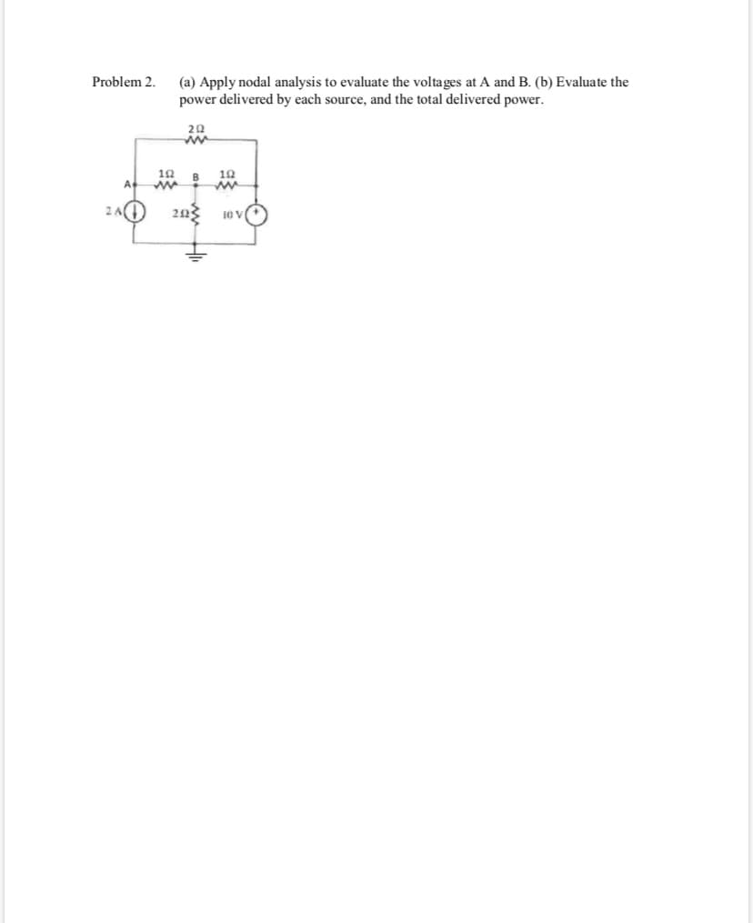
Problem 2 (a) Apply nodal analysis to evaluate the voltages at A and B. (b) Evaluate the power delivered by each source, and the total delivered power 20 10 B A. 20


Q: 2i, 50 4 V
A: Determine i1 using mesh analysis for the given circuit ?
Q: The input power to a 3-phase star connected load is measured as 5.5KW. If the line voltage and line…
A: Given 3 phase load Power, P = 5.5KW Line Voltage, VL = 424.2V Line Current, IL = 10.7A To…
Q: .Which of the following is not considered when finalizing the location of substation b) Nearness to…
A: To finalize the location of the substation various factors must be considered.
Q: A 417 V, 3 phase, 3 wire delta connected system supplies three resistive loads of 24 ohms each. The…
A: Given, A 417 V, 3 phase, 3 wire delta connected system supplies three resistive loads of 24 ohms…
Q: USING MESH determine the currents 36V I, 242 +
A:
Q: 1. Calculate I, in the 5ohms resistor using Thevenin's Theorem. 3A load Effective source
A: This question belongs to circuit theory . It is based on the concept of Thevenin's theorem . It is…
Q: 2. Determine the total resistance using delta to wye transformation. Also, find the total current.…
A:
Q: Calculate the direction and magnitude of the current through the 5-ohm resistor between points A and…
A: The given circuit is
Q: 240 V Μ 3 Ω 6Ω 10 Α 12 Ω +2 • 30 Ω + 60 V
A: In this question we need to find a a voltage V1 and V2 shown in the given circuit by using nodal…
Q: Consider the Wye (Y) network shown below. Which terminal has the largest equivalent resistance? 2R…
A: As per the guidelines of Bartley we supposed to answer first question only.
Q: 1.By using NODAL ANALYSIS solve the following electric circuit. 202 zi (a)Calculate the current in 4…
A:
Q: b. It is decided that the excess power generated from the preferred option will be transmitted to a…
A: Given data, Sending end voltage, Vs=33 KV Sending end phase angle 3.500 Receiving end phase angle…
Q: Q2: Draw the single line diagram of a substation having the following equipments: (1) Incoming…
A: To design the High voltage tranmission, Fast measuring and protection equipment is very important.…
Q: 3. Determine i1 using Mesh Analysis 2i, 50 4 V
A:
Q: II. Using nodal analysis solve for all the nodal voltages. 20 1, = 4 A +. 10 V 10 ww
A:
Q: EXAMPLE 2 For the network shown in the Figure determine: a) Determine re. b) Determine Z¡, Zo and A,…
A:
Q: The input power to a 3-phase star connected load is measured as 7.5KW. If the line voltage and line…
A: Right Answer option 1.2
Q: 6) For the Delta-connected circuit below, calculate (assuming balanced source): a. The line current…
A: The line voltage is 208 V. The given load is balanced delta having only resistive load, so the power…
Q: determine current I_1 (use Mesh (method
A:
Q: line currents (IR, Ty and 1B). (c) Determine the total real supply power (W) for Q1(b) based on the…
A:
Q: 15.Apply Mesh analysis to determine the Mesh currents and current through 5 ohm resistor Write all…
A:
Q: 35. Determine the wattmeter reading (stating whether or not the leads had to be reversed to obtain…
A: Wattmeter: Wattmeter reads the active power means it measures average power. This power is also…
Q: ind Ix using mesh analysis. 1220° V 10 j2N] 220°, 21, 21x
A: We will find out current by using of mesh analysis .
Q: 1) a) Calculate V1, V2, V3 and V4 voltages with using node voltage method OR calculate I1, 12 and I3…
A:
Q: Superposition problem. (use kvl, vdt) x.Determine the current flowing through the 2Ω resistor ( Ix'…
A:
Q: 3. a. Calculate the total impedance of the following circuit, and hence calculate ir b. Using…
A: It is given that: L1=2H=2ΩC1=3F=3ΩR1=6 ΩV=4 volt
Q: 32 20A Gov
A:
Q: 1. Using Nodal Analysis Method, evaluate the currents through the resistors of the circuit shown V,…
A:
Q: Calculate all the voltages, currents, and total power in this balanced Y – A system: Load Source +…
A:
Q: Ascertain the Actual values of the following given parameters 200mvA, 13.8kv generator which has a…
A: As per the guidelines of Bartleby we supposed to answer first three subparts of the question for…
Q: Q2: For the network shown in figure (2). determine Z, to ensure maximum power delivered to the load…
A: To solve above problem one should have idea about maximum power transfer theorem : Maximum power…
Q: R Rg R For the above circuit, determine the maximum power in Watts that can be delivered to a load…
A:
Q: Find hybrid parameters for the network in figure *. Μ 1Ω ΖΩ Μ 2Ω ΤΩ 41₁ Ω I,
A: In this question, We need to determine the hybrid parameters of the network? We are solving this…
Q: 2. To distribute the power at 415V over 3 phase 3 wire line, _____________ substation is used.
A:
Q: Find hybrid parameters for the I' network in figure ". ΤΩ 2Ω 2Ω ww ΤΩ •41 ΖΩ I, Ο +
A: In this question, We need to determine the hybrid parameters for the given network ? We are…
Q: 2. Using nodal analysis, find the power delivered by the dependent source (1) VTh 20 24V O 4AO
A: To calculate the power delivered by dependent source we will calculate voltage across it and the…
Q: Practice Problem In the circuit shown, calculate the nodal voltages V,V, & V 2A Vi V3 ww 100 201 50…
A:
Q: 4 8 30 V Re 15.2 4A B
A:
Q: 2.2 4K 20k V, = ?
A: Given circuit shown
Q: 2i, 50 4 V
A: According to the question we have to find the value of the i1.
Q: 5) Choose the correct answer with the explain: a) The maximum power transferred to the load is…
A: Maximum power theorem: The condition of maximum power dissipation across the load is RL=Ro. That…
Q: Practice Problem In the circuit shown, calculate the nodal voltages V,V, & V, 2A V2 V1 V3 ww 20 2 10…
A:
Q: Calculate the branch currents of the Circuit using the following 1. Kirchhoff's Law (KL) 2. Nodal…
A: In this question, Find the current in the each Branch using the 1. KCL and KVL 2. Nodal analysis 3.…
Q: A2 True/False Distribution of Electric power is done by 3 phase 2 wire system to industrial loads.
A:
Q: Calculate all the voltages, currents, and total power in this balanced Y – Y system: Source Load…
A:
Q: Question 4 The unbalanced A-load of Figure 4 is supplied by balanced line-to-line voltage of 440 V…
A: Given data Vab = 440 < 0 ° V Vbc = 440 < -120°. V Vac = 440 < 120 ° V Phase current =…
Q: stion here Draw the important components of a standard power system with a brief description.…
A: In an interconnected grid system multiple power system are connected to supply a load.
Q: A) A hydropower station has a head of 9 meter and three 10 MW units are installed to extr from the…
A:
Q: Practice Problem In the circuit shown, calculate the nodal voltages V,V & V, 2A V2 V1 V3 ww 20 2 10…
A: To find the node voltages V1 , V2 and V3
Q: blai 3 For the circuit shown, find the value of coupling coefficient "k", when the total ?(consumed…
A: The circuit diagram is given below, The total equivalent resistance of the circuit is,

Step by step
Solved in 8 steps with 7 images

- With generator conyention, where the current leaves the positive terminal of the circuit element, if P is positive then positive real power is delivered. (a) False (b) TrueA minimum of three wattemer should be used to measure power for a three phase balanced system. True FalseWhat is the total three-phase real power drawn by the two loads? Express your answer in Megawatts. Note that the power solved in the single-phase equivalent circuit is the power for a single-phase only.
- A short line having an impedance of (2 + j3) ohm interconnects two power stations A and B both operating at 11kV equal in magnitude and phase. To transfer 25 MW at 0.8 power factor lagging from A to B determine the voltage drop must be compensated by the booster so that the voltages are maintain the same at both ends.2.1 Two power stations, A and B, are synchronized at 66 kV. They are inter-connected by a transmission line with an inductive reactance of 6.7-Ω and resistance of 3.5-Ω per phase. The voltage of power station A is advanced with an angle of 10.5 degrees with respect to the voltage of power station B. The loading of power station B has a real power of 200 MW. The respective loads of the two power stations are as follows: Power station A: 165 MVA at a power factor of 0.819 lagging. Power station B: The reactive power consumed by the load is 155 Mvar. *Round off to two decimal places to every question 15.The active power loss within the interconnector (MW). 16.The reactive power loss within the interconnector (MVar). 17.The final loading of power station A (MVA) and it's angle2.1 Two power stations, A and B, are synchronized at 66 kV. They are inter-connected by a transmission line with an inductive reactance of 6.7-Ω and resistance of 3.5-Ω per phase. The voltage of power station A is advanced with an angle of 10.5 degrees with respect to the voltage of power station B. The loading of power station B has a real power of 200 MW. The respective loads of the two power stations are as follows:Power station A: 165 MVA at a power factor of 0.819 lagging.Power station B: The reactive power consumed by the load is 155 Mvar. *Round off to two decimal places to every question 18.The final loading of power station B (MVA) and it's angle 19.The reactive power received by power station A if the reactive power loading from power station A is to be reduced by 30% (MVar). 20.The required advancement angle at power station A to achieve the 30% reduction in reactive power loading of power station A (degrees).
- 2.1 Two power stations, A and B, are synchronized at 66 kV. They are inter-connected by a transmission line with an inductive reactance of 6.7-Ω and resistance of 3.5-Ω per phase. The voltage of power station A is advanced with an angle of 10.5 degrees with respect to the voltage of power station B. The loading of power station B has a real power of 200 MW. The respective loads of the two power stations are as follows: Power station A: 165 MVA at a power factor of 0.819 lagging. Power station B: The reactive power consumed by the load is 155 Mvar. *Round off to two decimal places in every question. Determine the following: 12.The interconnector current (kA)and it's angle 13.The reactive power received by power station A (MVar). 14.The active power received by power station B (MW).In a three phase overhead system , each line is suspended by a string of three insulators. The voltages across top unit and the middle unit are 8KV and 11KV respectively. Calculate a) ratio of shunt capacitance to self capacitance b) line voltage c) string efficiency.a) Find the ICA load current.b) Give the line voltage Vab.c) Calculate the total complex power on voltage sources.
- Derive conditions for economics dispatch when generating stations are connected in parallelIn a three phase overhead system , each line is suspended by a string of three insulator. The voltages across top unit and the middle unit are 8KV and 11KV respectively. Calculate a) ratio of shunt capacitance to self capacitance b) line voltage c) string efficiency6) The neutral current in a balanced Y-Y connected three-phase system is equal to zero True False