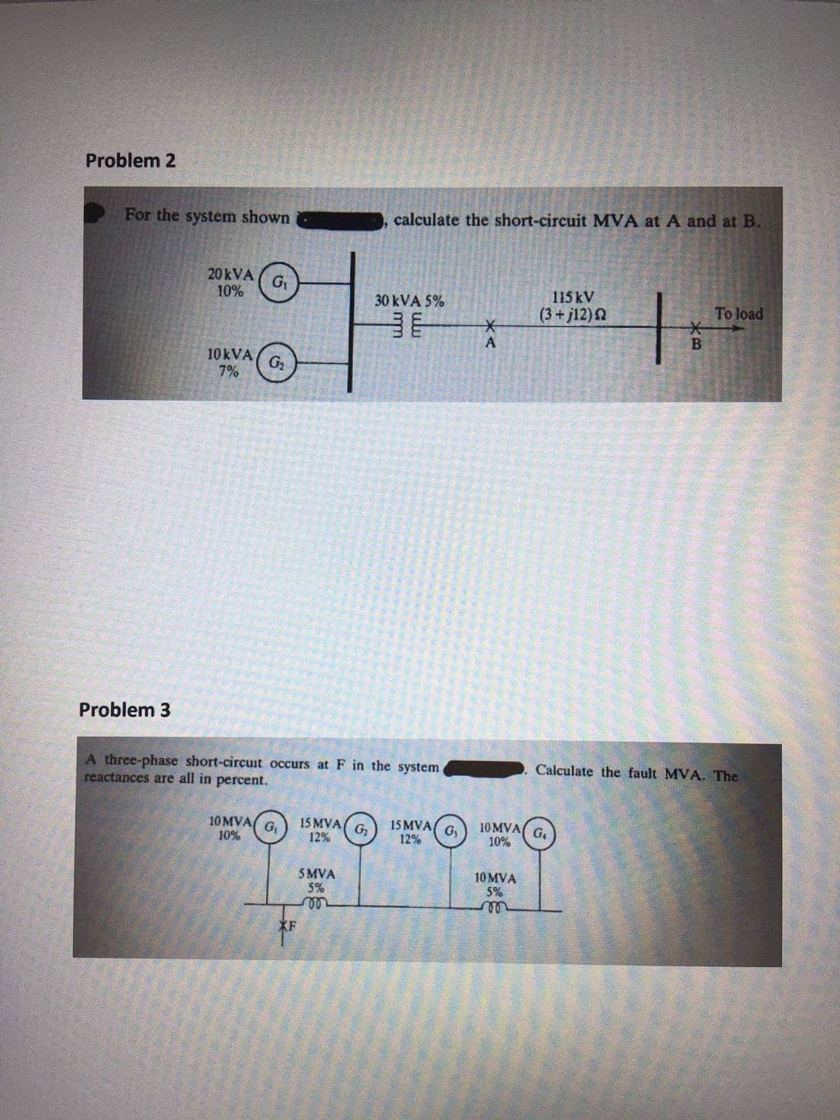
Problem 2 For the system shown calculate the short-circuit MVA at A and at B. 20 kVA 10% 30 kVA 5% 115 kV (3+ j12)2 To load 10KVA 7% G2 ulu m


Q: 2. A single phase 11 kV line with a length of 15 km is to transmit 500 kVA. The inductive reactance…
A: The transmission line is a long conductor with a specific design (bundled) for transporting large…
Q: Question 4.) An overhead, single-phase transmission line delivers 1.1MW at 33 kV at 0.8 p.f.…
A: According to question answer rule of Bartleby I have to solve first three sub part.
Q: Q2/ A single phase overhead transmission line delivers 1100 kW at 33 kV at 0•8 p.f. lagging. The…
A:
Q: Three different loads are connected in parallel across a 1000-volts (rms) single-phase source. Load…
A:
Q: A 15kV, 3 phase circuits feeds a load of 10,000 kW at a lagging load factor and the load current of…
A:
Q: A balanced three-phase source with grounded neutral has line-to-neutral voltages of 132.7906 volts…
A: The circuit can be drawn as
Q: There are two loads connected in parallel and powered from a 7200-V source. The first load is 50-kVA…
A:
Q: Hw1-3: 3-phase, 50HZ, 132KV power system of equivalent impedance 10+j35 Q with load 100+j25 Q. Find…
A: We are authorized to answer three one question at a time, since you have not mentioned which…
Q: Two balanced three phase loads are connected in parallel, the loads are L1= 20 kW at 0.7 pf lead,…
A: Active Power(P): The power which is deployed and absorbed by the electric circuit to do some useful…
Q: A single phase line has an impedance of 0.4+j2.7 ohms. The line feeds two -single phase loads that…
A:
Q: Q1 Figure 1 shows the online diagram of a three-phase power system. By selecting a common base of…
A: Given, Base power rating = 100 MVA Voltage rating = 22 kV Per unit rating of the generator = 0.18 pu…
Q: Two balance 3-phase loads are supplied by 830 volt, 60 Hz line. First load is star-connected with an…
A:
Q: A 11 kV,5 MVA, 10 km long uniformly distributed load radial feeder delivering a load of 3 MVA at the…
A: 10 km line 3MVA at the power factor 0.8 lagging. Radial distribution impedance z= 0.15+j0.5 ohm…
Q: A generating station has five section bus-bar connected with a tie-bar through 7·5% reactors rated…
A:
Q: An overhead 3-phase transmission line delivers 6000 kW at 32 kV at 0-6 p.f. lagging. The resistance…
A:
Q: For the system shown below with x=0.9 pu, determine static limit and corresponding voltage magnitude…
A: The system diagram is shown below, Where, x=0.9 pu
Q: A short 3-φ transmission line with an impedance of (5 + j 20) Ω per phase has sending end and…
A: Resistance of each conductor R=5 ohm Reactance of each conductor XL=20ohm Load power factor is 0.8…
Q: A single phase transmission line is delivering 500 kVA load at 2 kV. Its resistance is 0·2 Ω and…
A: Given,The inductive reactance is,
Q: Example 60 MVA, 13.8 kV a balance three phase load with 0.8 lagging power factor. Determine for the…
A:
Q: Q: 3 phase line delivers (3mw) at I Kv o8 layging power Factor the serles impedance of The line is…
A: According to question: The load line current is calculated as…
Q: Example 5. Two 1-phase transformers A and B rated at 250 kVA each are operated in parallel on both…
A: Given: SL=500∠36.86° KVAZA=1+j6ZB=1.2+j4.8 The formula for load shared by transformer A is given by…
Q: If the |Vs| = |Vr| = 25kV (Three Phase) and the line reactance X 8 ohm per phase. The maximum power…
A: NOTE: We’ll answer the first question since the exact one wasn’t specified. Please submit a new…
Q: 5. A 3-phase overhead transmission line has the following constants: Resistance/phase = 102…
A: The Correct solution can be achieved as follows.
Q: 11.65 The following loads are served by a balanced three-phase source: Load 1: 18 kVA at 0.8 pf…
A: In this question we need to find a power factor at the source
Q: Q/ A 3-phase, 4-wire system supplies loads which are unequally distributed in the three phases. An…
A: The sequence currents given are IR1 = 7.89 + j 0.732 A = 7.923883139 ∠5.30048° A…
Q: 2. One phase voltage of a three-phase wye-connected load is Vbn=340VZ+20°. Ib vab 340V@+20" Vbc Vca…
A: Fig: Given phasor diagram
Q: The circuit below shows a simple representation of one phase of a a short line in a power systen…
A: The power system solution is given below.
Q: A three phase distribution board of installed power 50KVA is supplied at 220/380V with a demand…
A:
Q: 400 kVA load at 12 kV. Its resistance is 62 and inductive reactance is 8 Q. If the load power factor…
A:
Q: 1. A three phase, 3 wire, CBA system, with the line voltage VAB = 300cis0°, has the following line…
A:
Q: If the Ival = |vrl= 30kV (Three Phase ) and the line reactance X = 10 ohm per phase. The maximum…
A: Given, Sending end voltage, VS=30 kV Receiving end voltage, VR=30 kV The Line reactance, XL=10 Ω
Q: A single phase transmission line is delivering 500 kVA load at 2 kV. Its resistance is 0·2 Ω and…
A: Given a single phase transmission line with Load : 500 KVA at 2 KV Resistance=0.2Ω inductive…
Q: Question 1 Assume that an area is served by a three phase main feeder (K = 0.015) & two lateral (K =…
A: Part (a): It is given that the 144 customers per lateral with a maximum demand of 4.4 kVA/customer.…
Q: 1. Assume that a 2.5-kV 1-phase circuit feeds a load of 450 kW at a lagging load power factor and…
A: Calculate the initial power factor of the circuit. Ps=VIcosϕcosϕ=PsVI=450×103 W2.5×103 V215 A=0.837
Q: A- Consider the system shown below. Phase b is open due to conductor break. Calculate the sequence…
A: Since you have asked multiple questions, we will solve the first question for you. If you want any…
Q: One conductor of a three-phase line is open. The current flowing to the A-connected load through…
A: Let Ia , Ib and Ic are the line currents flowing through the load and I0 is the zero-sequence…
Q: A single phase overhead transmission line delivers 1100 kW at 33 kV at 0 8 p.f. lagging. The total…
A:
Q: 3- The single phase loads in the circuit can be described as follows: Load 1 absorbs an average…
A:
Q: 5. A 3-phase overhead transmission line has the following constants : Resistance/phase Inductive…
A:
Q: A three-phase impedance load consists of a balance A load in parallel with a balance Y load. The…
A:
Q: An overhead 3-phase transmission line delivers 6000 kW at 22 kV at 0.9 p.f. lagging. The resistance…
A: In the 3 phase transmission line Resistance and inductance are given of the transmission line. At…
Q: 3. Two balanced loads are connected in parallel to a three-phase, 460-V source. Load A is 900 kVA at…
A: In this question, we will find total KVA and overall power factor of combined system...
Q: Two parallel connected loads A and B are supplied by a 440 V line to line, 3-phase, 60 Hz generator.…
A: Current: It is the time rate of the change of the charges. It flows from high voltage to low voltage…
Q: Q5. In the 3-phase system shown below, phase a is on no load and phases b and c are short circuited…
A:
Q: A power system network as shown in Figure 1 comprises of synchronous generators, transformers,…
A: Given single phase transformer with Shunt resistance Rsh=360 ΩShunt reactance Xsh=290 ΩShort…
Q: Answer the question in the below Image. A single phase transmission line is delivering 500 kVA load…
A:
Q: A single phase transmission line delivers 1500 kW at 33 kV at 0.8 p.f. lagging. The total resistance…
A: Given P = 1500kW V = 33kV Pf = 0.8 lagging ZL = (10+j15)Ω Sending end voltage(VS): ? Sending end…
Q: reactance.: a) Find The steady fault current due to three phase short circuit on B b) Find short…
A: In this question, fault occurs at point B..We have to find out fault current and short circuit MVA…
Q: The following figure is a single line diagram three phase four wire Y grounded primary feeder 11KV..…
A: First, determine the resistance of each section of transmission line, ROA=1mi×0.4ohm/mi=0.4…
Q: A single phase load of 100 kVA is connected acro: lines b,c of a 3-phase supply of 3.3 kV.Determine…
A: From given data we will find Currents in all three phases. Now we will write phase sequence currents…

Step by step
Solved in 5 steps with 4 images


- a) Draw the sequence network and calculate the sub-transient fault current for a dead short circuit on one phase to ground at bus 4 with fault impedance j1.78 p.u for the system shown in Fig. The system data's are Machine 1: Xd”=j0.21p.u , X2=j0.4p.u; X0= j0.55p.u ; Machine 2: Xd”=j0.21p.u , X2=j0.4p.u; X0= j0.55p.u ; Transformers T1 and T2 : X1=X2=X0= j1.2p.u The transmission line reactance X1=X2= j0.21p.u and X0=0.97 p.u.A balanced load with ZR = ZB = ZY = ……<00 Ω was supplied a three phase 50 Hz, 100 V between line (balanced source). A fault on phase ‘B’ causes an open circuit, which unbalanced the load as shown in Figure 4. Similarly, a fault on the load of phase ‘Y’ cause a short-circuit, which unbalanced the load as shown in Figure 5. Using complex notation determine and analyse the individual phase currents and the neutral current in both figure.Q: For the following OLD, take Sg = 50 MVA and VB = 22 kV at thetransmission line to find the short circuit current if a 3-ph fault occurs atthe middle of transmission line.15 MVA20 MVAX = j0.6 pu(15:35) kVG-EX = j0.3 pu25 MVA(40:15) kV15 MVA(6+j8) Q23 kVM18 kVT.LX = j0.5 puT1T2´x = j0.3 pu
- The 60 mile, 115 kV line GH (Figure P12.8) is operating with the voltages ateach end 30° out of phase when a three-phase fault occurs at 80% of the distance from bus G. This fault has 12 Ω arc resistance. The currents flowing tothe fault are as shown and are in per unit at 100 MVA, 115 kV.d. Determine if the zone 1 mho unit at H set for 90% of the line GH can operate for this fault. Assume that the angle of the mho characteristic is 75°.e. Describe how this three-phase fault can be cleared by the line distance relays.Q5: A SL-G fault occurs on the low voltage side of a transformer that connects a motor to a generator at generating plant. The rated values for each element are:M: 0.6 kV, 5 MVA, X1 = X2 = 20%, X0 = 4%, grounded through 2% reactance.T: 3-single phase units, each is: (2400 Grounded Y: 600 Δ) V, 2.5 MVA, Xt = 10%.G: 4.16 kV, 7.5 MVA, X1 = X2 = 10%, X0 = 5%, grounded through 5% reactance.Draw the sequences networks and determine the fault current in Amperes. (Take the generator ratings as a base).In the shown below power system, both generators G1 and G2 emf’s are equal.All the system data are shown on the system diagram.a) Draw the system diagram in per unit using (MVA)base = 75 and (KV)base =20 KV in the generators side.b) Calculate the three-phase balanced short circuit current (If) at busbar 3 inAmpere and the fault level (MVA)sc in MVA.c) If the fault at busbar 3 is a line-to-line fault, calculate the fault current inAmpere and the fault level (MVA)sc in MVA.
- In a short circuit test on 132 kV, 3-phase system, the breaker gives the following results: Power factor of the fault = 0.45. Recovery voltage 0.9 time of full line voltage. The breaking current is symmetrical. The restriking transient has a natural frequency of 15 kHz. Calculate the rate of rise of restriking voltage (RRRV) in the following types of faults: (1) Grounded fault (2) Undergrounded fault.The one line diagram of a three phase power system is as shown in Figure 7 Impedances are marked in per unit on a 100 MVA, 400 kV base The load at bus 2 is S2 15.93 MW - j 33.4 MVar, and at bus 3 is S3 77 MW + j 14 MVar It is required to hold the voltage at bus 3 at 400 kV Working in per unit, determine the voltage at buses 2 and 1A balanced three-phase source with grounded neutral has line-to-neutral voltages of 120 volts with an-bn-cn sequence. This source has an internal series impedance of 0.15+j2.0 ohms per phase. It supplies power to an unbalanced three-phase delta load with impedances: Zab = 30+j40; Zbc = 50-j40; Zca = 65+j25 ohms. If there is a double-line-to-ground fault at lines b and c load-side, what is the magnitude of the fault current injected to the ground in amperes?
- A 25 MVA, II kV generator has X"d=0.2 p.u. X2 = 0.3p.u. and X0=0.1 p.u. Tht neutral of generator is solidly grounded. Determine the subtransient current in the generator and the line to line voltages for subtransient condition when a Y-B-G fault occurs at the generator terminals. Assume prefault currents and fault resistance to be zero.Line impedances for the power system shown in Figure 1 are Z12 = Z23 = 3.0 + j40.0 Ω, and Z24 = 6.0 + j80.0 Ω. Reach for the zone 3 B12 impedance relays is set for 100% of line 1–2 plus 120% of line 2–4. (a) For a bolted three-phase fault at bus 4, show that the apparent primary impedance “seen” by the B12 relays is Zapparent = Z12 + Z24 + (I32/I12)Z24 where (I32/I12) is the line 2–3 to line 1–2 fault current ratio. (b) If |I32/I12| > 0.20, does the B12 relay see the fault at bus 4?A synchronous generator is feeding its rated power of 250 MW to a large 60 Hz network over a double circuit transmission The maximum steady state power that can be transmitted over the line with both circuits in service is 500 MW and is 350 MW with any one out of service. A solid three-phase fault occurring at the network-end of one of the lines causes it to trip. If inertia constant is H = 3.5 s, calculate the critical clearing angle and critical clearing time in which the circuit breakers must trip so that synchronism is preserved.