Q 3) The schematic diagram of a generator supplying two loads through a distribution system is shown below. Load A draws 8kW at a leading pf of 0.8, while load B draws 10kW at a 0.6 lagging pf. The terminal voltage at load B is 215 Vrms. Determine the voltage at the generator as well as the real power P, reactive power Q, and apparent power S, supplied by the generator. Assuming the terminal voltage at load B is the reference phasor and has the zero phase angle, i.e., the phasor of terminal voltage at load B is 21520° Vrms- 0.4 2 J0.8 N 0.40 J0.8 Q Load Load A B
Q 3) The schematic diagram of a generator supplying two loads through a distribution system is shown below. Load A draws 8kW at a leading pf of 0.8, while load B draws 10kW at a 0.6 lagging pf. The terminal voltage at load B is 215 Vrms. Determine the voltage at the generator as well as the real power P, reactive power Q, and apparent power S, supplied by the generator. Assuming the terminal voltage at load B is the reference phasor and has the zero phase angle, i.e., the phasor of terminal voltage at load B is 21520° Vrms- 0.4 2 J0.8 N 0.40 J0.8 Q Load Load A B

Power System Analysis and Design (MindTap Course List)
6th Edition
ISBN:9781305632134
Author:J. Duncan Glover, Thomas Overbye, Mulukutla S. Sarma
Publisher:J. Duncan Glover, Thomas Overbye, Mulukutla S. Sarma
Chapter2: Fundamentals
Section: Chapter Questions
Problem 2.30MCQ: Under balanced operating conditions, consider the three-phase complex power delivered by the...

Related questions

Question
solve the following problem
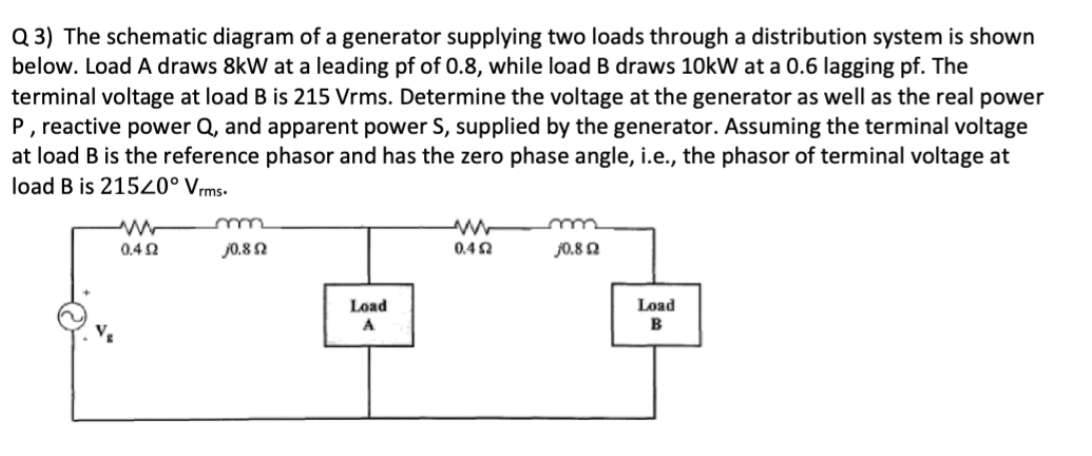
Transcribed Image Text:Q 3) The schematic diagram of a generator supplying two loads through a distribution system is shown
below. Load A draws 8kW at a leading pf of 0.8, while load B draws 10kW at a 0.6 lagging pf. The
terminal voltage at load B is 215 Vrms. Determine the voltage at the generator as well as the real power
P, reactive power Q, and apparent power S, supplied by the generator. Assuming the terminal voltage
at load B is the reference phasor and has the zero phase angle, i.e., the phasor of terminal voltage at
load B is 21520° Vrms-
0.4 2
J0.8 N
0.40
J0.8 Q
Load
Load
A
B
Expert Solution
This question has been solved!
Explore an expertly crafted, step-by-step solution for a thorough understanding of key concepts.

Step by step
Solved in 3 steps with 2 images

Knowledge Booster


Learn more about
Need a deep-dive on the concept behind this application? Look no further. Learn more about this topic, electrical-engineering and related others by exploring similar questions and additional content below.Recommended textbooks for you
Power System Analysis and Design (MindTap Course …
Electrical Engineering
ISBN:
9781305632134
Author:
J. Duncan Glover, Thomas Overbye, Mulukutla S. Sarma
Publisher:
Cengage Learning

Delmar's Standard Textbook Of Electricity
Electrical Engineering
ISBN:
9781337900348
Author:
Stephen L. Herman
Publisher:
Cengage Learning
Power System Analysis and Design (MindTap Course …
Electrical Engineering
ISBN:
9781305632134
Author:
J. Duncan Glover, Thomas Overbye, Mulukutla S. Sarma
Publisher:
Cengage Learning
Delmar's Standard Textbook Of Electricity
Electrical Engineering
ISBN:
9781337900348
Author:
Stephen L. Herman
Publisher:
Cengage Learning