Q Find Vs, Vesa Vo and which transistor is ON and which is OFF for CMOS circuit whes the V; is -5V and the Vss is + 10V 02 Draw the ontpur voltage (V,) of the circit shown in figure (1), for the input voltage V= 13Sinwt E D Vi Ve S 02v R=1k0 Fig. 1 Q3: Sketeh the output voltage (Vo) of the clamper cirenit showns in figwe (2) for the uput voltage V, = -2 + 12Sinwt L ; Vie—{ Vo E=sV m R Fig.2 Qi Sketch the output voltage (V,) for the circuit and the imput voltage (V) shown i figure (3).
Q Find Vs, Vesa Vo and which transistor is ON and which is OFF for CMOS circuit whes the V; is -5V and the Vss is + 10V 02 Draw the ontpur voltage (V,) of the circit shown in figure (1), for the input voltage V= 13Sinwt E D Vi Ve S 02v R=1k0 Fig. 1 Q3: Sketeh the output voltage (Vo) of the clamper cirenit showns in figwe (2) for the uput voltage V, = -2 + 12Sinwt L ; Vie—{ Vo E=sV m R Fig.2 Qi Sketch the output voltage (V,) for the circuit and the imput voltage (V) shown i figure (3).

Introductory Circuit Analysis (13th Edition)
13th Edition
ISBN:9780133923605
Author:Robert L. Boylestad
Publisher:Robert L. Boylestad
Chapter1: Introduction
Section: Chapter Questions
Problem 1P: Visit your local library (at school or home) and describe the extent to which it provides literature...

Related questions

Question
Q Find Vs, Vesa Vo and which transistor is ON and which is OFF for CMOS circuit whes the V; is -5V and the Vss is + 10V 02 Draw the ontpur voltage (V,) of the circit shown in figure (1), for the input voltage V= 13Sinwt E D Vi Ve S 02v R=1k0 Fig. 1 Q3: Sketeh the output voltage (Vo) of the clamper cirenit showns in figwe (2) for the uput voltage V, = -2 + 12Sinwt L ; Vie—{ Vo E=sV m R Fig.2 Qi Sketch the output voltage (V,) for the circuit and the imput voltage (V) shown i figure (3).
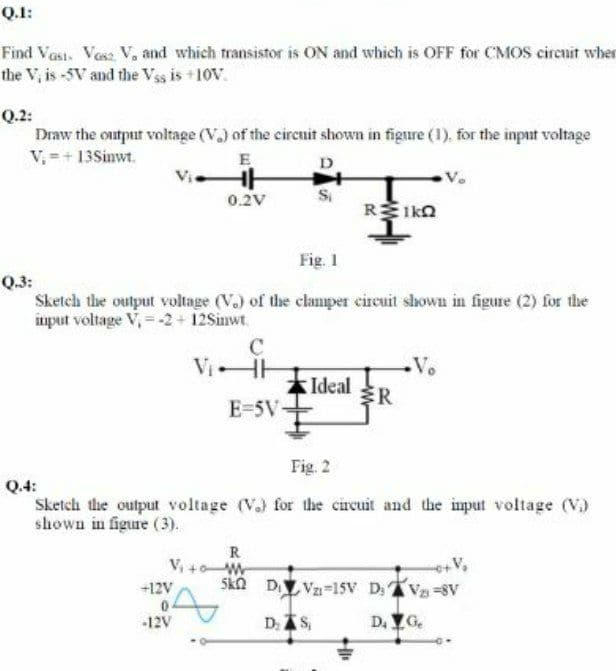
Transcribed Image Text:Q.1:
Find Vest. Vesa Va and which transistor is ON and which is OFF for CMOS circuit wher
the V, is -5V and the Vss is +10V.
Q.2:
Draw the outpur voltage (V.) of the circnit shown in figure (1), for the input voltage
V, =+13Sinwt.
E
D
0.2V
R1ka
Fig. 1
Q.3:
Sketch the output voltage (V.) of the clamper eircuit shown in figure (2) for the
input voltage V, = -2 + 12Sinwt.
ViHH
Vo
Ideal
ER
E=5V-
Fig. 2
Q.4:
Sketch the output voltage (V.) for the circuit and the imput voltage (V)
shown in figure (3).
R
V, +0W
+12V
D V=15V D, V-8V
-12V
D. AS,
D. YG.
Expert Solution
This question has been solved!
Explore an expertly crafted, step-by-step solution for a thorough understanding of key concepts.

Step by step
Solved in 3 steps

Knowledge Booster


Learn more about
Need a deep-dive on the concept behind this application? Look no further. Learn more about this topic, electrical-engineering and related others by exploring similar questions and additional content below.Recommended textbooks for you
Introductory Circuit Analysis (13th Edition)
Electrical Engineering
ISBN:
9780133923605
Author:
Robert L. Boylestad
Publisher:
PEARSON

Delmar's Standard Textbook Of Electricity
Electrical Engineering
ISBN:
9781337900348
Author:
Stephen L. Herman
Publisher:
Cengage Learning

Programmable Logic Controllers
Electrical Engineering
ISBN:
9780073373843
Author:
Frank D. Petruzella
Publisher:
McGraw-Hill Education
Introductory Circuit Analysis (13th Edition)
Electrical Engineering
ISBN:
9780133923605
Author:
Robert L. Boylestad
Publisher:
PEARSON
Delmar's Standard Textbook Of Electricity
Electrical Engineering
ISBN:
9781337900348
Author:
Stephen L. Herman
Publisher:
Cengage Learning
Programmable Logic Controllers
Electrical Engineering
ISBN:
9780073373843
Author:
Frank D. Petruzella
Publisher:
McGraw-Hill Education

Fundamentals of Electric Circuits
Electrical Engineering
ISBN:
9780078028229
Author:
Charles K Alexander, Matthew Sadiku
Publisher:
McGraw-Hill Education

Electric Circuits. (11th Edition)
Electrical Engineering
ISBN:
9780134746968
Author:
James W. Nilsson, Susan Riedel
Publisher:
PEARSON

Engineering Electromagnetics
Electrical Engineering
ISBN:
9780078028151
Author:
Hayt, William H. (william Hart), Jr, BUCK, John A.
Publisher:
Mcgraw-hill Education,