Q: Shear force acting on a section of a bea is 60 kn. The Section of the beam is of T- Sha of dimensions 120 mm x 120 mm x 20mm in figure below. calculate the shear stress at neutral axis and at th junction of the w and the flange (Point A, B, C, D and E) as Shor ↓k 120mm. F1 120 mm. Joomm. 20mm C D 20mm E
Q: Shear force acting on a section of a bea is 60 kn. The Section of the beam is of T- Sha of dimensions 120 mm x 120 mm x 20mm in figure below. calculate the shear stress at neutral axis and at th junction of the w and the flange (Point A, B, C, D and E) as Shor ↓k 120mm. F1 120 mm. Joomm. 20mm C D 20mm E

Mechanics of Materials (MindTap Course List)
9th Edition
ISBN:9781337093347
Author:Barry J. Goodno, James M. Gere
Publisher:Barry J. Goodno, James M. Gere
Chapter6: Stresses In Beams (advanced Topics)
Section: Chapter Questions
Problem 6.10.1P: Determine the shape factor f for a cross section in the shape of a double trapezoid having the...

Related questions
Question
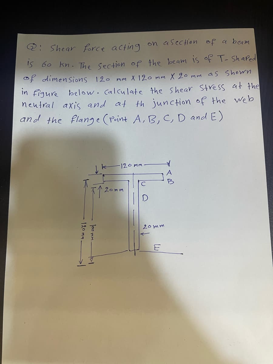
Transcribed Image Text:Q: Shear force acting on a section of a beam
is 60 kn. The Section of the beam is of T- Shaped
of dimensions 120 mm X 120 mm X 20 mm as shown
in figure below. calculate the shear stress at the
neutral axis and at junction of the web
and the flange (Point A, B, C, D and E)
120mm.
个 200
loomm
-120mm
20mm
20mm
E
Expert Solution
This question has been solved!
Explore an expertly crafted, step-by-step solution for a thorough understanding of key concepts.

Step by step
Solved in 4 steps with 3 images

Knowledge Booster


Learn more about
Need a deep-dive on the concept behind this application? Look no further. Learn more about this topic, mechanical-engineering and related others by exploring similar questions and additional content below.Recommended textbooks for you
Mechanics of Materials (MindTap Course List)
Mechanical Engineering
ISBN:
9781337093347
Author:
Barry J. Goodno, James M. Gere
Publisher:
Cengage Learning
Mechanics of Materials (MindTap Course List)
Mechanical Engineering
ISBN:
9781337093347
Author:
Barry J. Goodno, James M. Gere
Publisher:
Cengage Learning