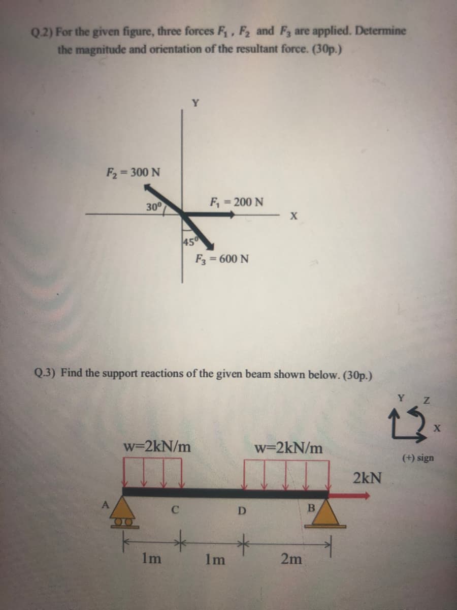
Q.2) For the given figure, three forces F,, F2 and F3 are applied. Determine the magnitude and orientation of the resultant force. (30p.) Y = 300 N 300 F, = 200 N 450 F = 600 N %3D


Q: Example : Replace the three forces acting on the bent beam by a single equivalent force R. Specify…
A: Static equilibrium: A body is said to be in static equilibrium if it satisfies the following…
Q: Replace the loading on the frame by a single resultant force. Suppose that Fi = 250 lb , F2 = 90 lb…
A: Given data as per question F1 =250 lb F2 = 90 lb M =500 lb. ft considering horizontal forces as…
Q: Q/ Replace the loading on the frame by a single resultant force. Specify where its line of action…
A: According to the given information we have to equate the resultant force along the x-axis is…
Q: F, = 250 N 45° F= 200 N 4 O F= 400 N A (a)
A:
Q: Q. 1 For the figure 1, determine the required tension in cable BC, if the resultant of three forces…
A: Since we only answer one question at a time, we will answer the first one. Please resubmit the…
Q: Problem 2.The resultant of a certain system of forces has the x and y components shown in the figure…
A:
Q: Q.1) For the figure shown if the tension in cable AB is 15 kN, and 32.5 m long. Determine (a) the x,…
A: tension in cable AB = 15 kN length of cable AB = 32.5m length of pole AO = 28m angle made at ABO =…
Q: Replace the three forces acting on the shaft by a single resultant force. Suppose that F1 = 650 lb…
A: Given data as per the question F1 = 650 lb F2 = 400 lb F3 = 260 lb . calculating the horizontal…
Q: . Determine the resultant of the three concurrent forces. y F=50N F=10N 14 60° X F=60N 2.
A: From figure F1=50 N F2=10 N F3=60 N FBD Now find the angle made by triangle on Resultant Force…
Q: Practice Problem 2.4.7: Knowing that the forces P and Q are equivalent to a single force R that…
A: Given, Q =30 lb
Q: Q5: The forces F1=6 kN, F2= 5 kN, and F3= 8 kN as shown in the Figure below, all of which act on…
A: Given data: The 1st force is F1=0.6 kN=600 N The 2nd force is F2=0.5 kN=500 N The 3rd force is…
Q: 4)Find the true magnitude and direction of the support forces A,B Fig4.4 8' 3' 3' -400lb B Fig4.4
A: Consider Free Body Diagram: Balancing Forces along X direction:RB*cos60=RAH .....(1)Balancing…
Q: Example : Replace the three forces acting on the bent beam by a single equivalent force R. Specify…
A: Given Cantilever beam as shown below
Q: Problem 3 w2 kN/m 7x kN/m From the figure, w1=11kN/m, w2=15KN/m w1 kN/m 1. Find the resultant of the…
A:
Q: Problem #1: From the given set of parallel forces shown in the figure, determine the Resultant force…
A: Problem #1 , Given data, Q= 40 KN T= 60 KN P= 45 KN W= 70 KN
Q: 1. The body shown in the figure is acted on by four forces, determine the resultant. ty 448N w/ 2:1…
A: Given:- To Find:- Resultant force (R)
Q: 4. The Distributed load is shown in the figure. Determine; a. the magnitude of the equivalent 42 N/m…
A:
Q: 1. The resultant force system has x and y components as shown in the figure. a. Draw the rotated…
A: Rotation of force with axis = Cos Component of that force in the axis direction and Sin Component of…
Q: Replace the loading acting on the beam by a single resultant force. Specify where the force acts,…
A:
Q: Q.4) Resolve the force 80 kN into two components, one along OM and the other along ON 80KN 450 130 M
A: Given data: F = 80 N Need to determine the components of the force along OM and ON direction.
Q: Ex.4.6 Three concurrent forces P,Q and F have a resultant of 5 lb directed forward and up to the…
A: Given, R=5 lbθx=600, θy=600, θz=450P=20 lbQ=20 lbP(2,1,4)Q(5,2,3)
Q: Question 7 The antenna tower is supported by three cables. If the forces of these cables acting on…
A:
Q: 4. A dirigible is tethered by a cable attached to its cabin at B. If the tension in the cable is…
A:
Q: if the Resaltant For Forces shownin figure equal To ClooN) upward, find F pO;? 450N 300 N
A:
Q: Find two forces, one acting along rod AB and one along rod CB, which when added, are equivalent to…
A:
Q: 2.3 The magnitudes of the three forces applied to the eye bolt are T₁ 550 N, T₂ = 200 N, and T3 =…
A:
Q: Q// Determine the resultant force in figure bellow, and specify where it acts measured from point B.…
A:
Q: Homework Condition: curved bar OABC, force F Acting at C point and in the plane ABC OA along y,…
A: This problem will be solved in two steps. Firstly, we have to find the moment of the given force…
Q: Practice Problem 2.4.7: Knowing that the forces P and Q are equivalent to a single force R that…
A: According to the condition of equilibrium, the moment about point A should be equal to zero. Net…
Q: 2. The trapezoidal force distribution shown in the figure acts on beam AB. Determine the magnitude…
A:
Q: Determine the components of the moment (Mx, My, Mz) that the F force will create at the point C in…
A:
Q: Consider three forces P1, P2, and P3, where P1 = 823 N, P2 = 441 N, and P3 = 420 N. Determine the x…
A:
Q: Q22](problem 2/28i p37) (sāl2) Determine the resultant R' of the two forces Shown in fiqure, and…
A: Solution: Some of the forces in the horizontal direction is given by, ∑Fx=-…
Q: Replace the loading acting on the beam by a single resultant force. Take F₁ = 450 N, F₂ = 290 N, F3…
A: Given Force, F1 = 450 N F2 = 300 N F3 = 700 N Moment, M = 1500 N.m Find…
Q: Practice Problem 2.4.4: Determine P and 0 so that the three forces shown are equivalent to the…
A: Given: R=85i+20j x and y-component of the force resultant are Rx=85 kNRy=20 kN
Q: 3)Find the true magnitude and direction of the forces in each member AC,CD Fig4.3
A: Given data Given force system
Q: 400 N/m 200 N/m B 8 m
A:
Q: 1.6.11 If the axial force in the tie rod DE is P = 1000 N, determine the two nonrectangular…
A:
Q: For F = 70 lb, compute the combined moment of the two forces about (a) point O, (b) point C, (c)…
A:
Q: Q.5) Three forces are applied to bracket as shown in figure below. Replace the given force system by…
A: Given: The force along BE, FBE = 600 N The force at C, Fc = 800 N The force at D, Fd = 1000 N
Q: Q3) For the concurrent coplanar force system shown below, calculate the magnitude and the slope of…
A: Mechanical Equilibrium: A body is said to be in mechanical equilibrium if it satisfies the following…
Q: 24: For the forces system in figure if the resultant mom ent aboul point A is equal to (Zero) find…
A: Mechanical Equilibrium: A body is said to be in mechanical equilibrium if it satisfies the following…
Q: Example : Replace the three forces acting on the bent beam by a single equivalent force R. Specify…
A:
Q: (Q1] Replace the system shown below by a single force at B and a couple. 700 N |30° 450 N 300 N 60…
A:
Q: Problem 3 w2 kN/m 7x kN/m From the figure, w1=9kN/m, w2=13KN/m 1. Find the resultant of the forces…
A:
Q: A rectangular plate is supported by three cables as shown. 480 250 D 360 130 320 360 450 C…
A:
Q: Problem-1 Tension in cable BC is 725 N; determine the resultant of the three forces exerted at point…
A: To find : The resultant of the three forces exerted at point B of beam AB. Given data : The tension…
Q: Problem #1 The inclined pole is subjected to a 5 kN magnitude force vector F acting from point B…
A:
Q: Determine the magnitude of the resultant force (in N) of the coplanar force system shown in the…
A: For finding out the resultant force , there is no need of moment. Let us take upward direction as…
Q: Q4 / 2. For the force system shown in ( fig.4) below the resultant; (R) is equal to ( 500N) , the…
A: from the above figure given that resultant is R=500N the value of Q will be 500*sin(25) why…

Step by step
Solved in 2 steps with 2 images


- The beam ABC shown in the figure is simply supported at A and B and has an overhang from B to C. The loads consist of a horizontal force P1= 4,0 kN acting at the end of a vertical arm and a vertical force P2= 8.0 kN acting at the end of the overhang, Determine the shear force Fand bending moment M at a cross section located 3,0 m from the left-hand support. Note: Disregard the widths of the beam and vertical arm and use centerline dimensions when making calculations, Find the value of load A that results in V = 0 at a cross section located 2.0 m from the left-hand support. If P2= 8.0 kN, find the value of load P1that results in M = 0 at a cross section located 2,0 m from the left-hand support.Two identical, simply supported beams AB and CD are placed so that they cross each other at their midpoints (sec figure). Before the uniform load is applied, the beams just touch each other at the crossing point. Determine the maximum bending moments (mab)max* and (MCD)max beams AB and CD, respectively, due to the uniform load if the intensity of the load is q = 6.4 kN/m and the length of each beam is L = 4 m.A beam supporting a uniform load of intensity q throughout its length rests on pistons at points A, C and B (sec figure). The cylinders are filled with oil and are connected by a tube so that the oil pressure on each piston is the same. The pistons at A and B have diameter d1and the piston at C has diameter D2. (a) Determine the ratio of d2to d1so that the largest bending moment in the beam is as small as possible. Under these optimum conditions, what is the largest bending moment Mmaxin the beam? What is the difference in elevation between point C and the end supports?
- Find expressions for shear force V and moment M at v = L/2 of beam AB in structure (a). Express V and M in terms of peak load intensity q0and beam length variable L. Repeat for structure (b) but find Fand M at m id-span of member BC.A cylindrical brick chimney of height H weighs w = 825 lb/ft of height (see figure). The inner and outer diameters are d1= 3 ft and d2= 4 ft, respectively. The wind pressure against the side of the chimney is p = 10 lb/ft2 of projected area. Determine the maximum height H if there is to be no tension in the brickwork.A sandwich beam having steel faces enclosing a plastic core is subjected to a bending moment M = 5 kN · m. The thickness of each steel face is 1 = 3 mm with modulus of elasticity E = 200 GPa, The height of the plastic core is hp= 140 mm, and its modulus of elasticity is Ep= 800 MPa. The overall dimensions of the beam are h = 146 mm and h = 175 mm. Using the transformed-section method, determine the maximum tensile and compressive stresses in the faces and the core.
- A fiberglass pipe is lifted by a sling, as shown in the figure. The outerdiameter of the pipe is 6,0 in., its thickness is 0.25 in,, and its weightdensity is 0,053 1b/in3 the length of the pipe is L = 36 ft and the distancebetween lifting points is s = 11 ft.a. Determine the maximum bending stress in the pipe due to its ownweight,b. Find the spacing s between lift points which minimizes thebending stress. What is the minimum bebding stress?c. What spacing s leads to maximum bending stress? What is thatstress?The horizontal beam ABC of an oil-wellpump has the cross section shown in the figure. If thevertical pumping force acting at end C is 9 kips andif the distance from the line of action of that force topoint B is 16 ft, what is the maximum bending stressin the beam due to the pumping force?Draw the shear-force and bending-moment diagram for the beam shown. Assume the upward reaction provided by the ground to be uniformly distributed. Let a = 5.0 ft, b = 3.4 ft, P = 25 kips, and w = 1.1 kips/ft. Label all significant points on each diagram. Determine the maximum value of (a) the internal shear force and (b) the internal bending moment.Note that answers may be positive or negative. Here, "maximum" refers to the largest magnitude value, but you should enter your shear force and bending moment with the correct sign, using the sign convention presented in Section 7.2 of the textbook. If the magnitudes of the largest positive and largest negative values are the same, enter a positive number.
- Consider the two-member frame shown. Suppose that w1 = 280 N/m , w2 = 450 N/m . Follow the sign convention. A) Determine the internal normal force at point E. NE = ? B) Determine the internal shear force at point E. VE = ? C) Determine the internal moment at point E. ME = ?A beam subjected to a bending test has internal vertical shear force V=2000N. The cross-sectional area is shown in the figure. What is the maximal shear stress? (Hint: the area moment (Q) is given by bh2/8, and the area moment of inertia of the cross-sectional area is equal to bh3/12, b is the width, h is the height).Question 1) in FIG loading condition is given beam F force F = 65 kN , first distributed load W 1 = 41 kN / m , w 2 distributed load w 2 = 51 kN / m , θ angle θ = 48 ° and L length of L = 5 m . According to this; Question 1-A) B at the point y direction ( B y ) Determine the support reactions. (Enter yourresultwithout writing kN units.) Question 1-B) to the point in y direction ( A y ) Determine the support reactions. ( Enter yourresult without writing kN units.) Question 1-C) to the point in x direction ( A x ) Determine the support reactions. ( Enter yourresult without writing kN units.)