Q1: At a certain section, beam has the cross-section shown in Figure (1) below. The beam is simply supported at its ends with length of 3 m and carries a central concentrated load of 450 kN. For a section at 1 m from the left-hand support, determine the shear stress only at (a) the neutral axis and (b) x. 25 mm 20 mm -X- 12 mm 500 N.A. 500
Q1: At a certain section, beam has the cross-section shown in Figure (1) below. The beam is simply supported at its ends with length of 3 m and carries a central concentrated load of 450 kN. For a section at 1 m from the left-hand support, determine the shear stress only at (a) the neutral axis and (b) x. 25 mm 20 mm -X- 12 mm 500 N.A. 500

Chapter9: Application Of Influence Lines
Section: Chapter Questions
Problem 11P

Related questions

Concept explainers
Question
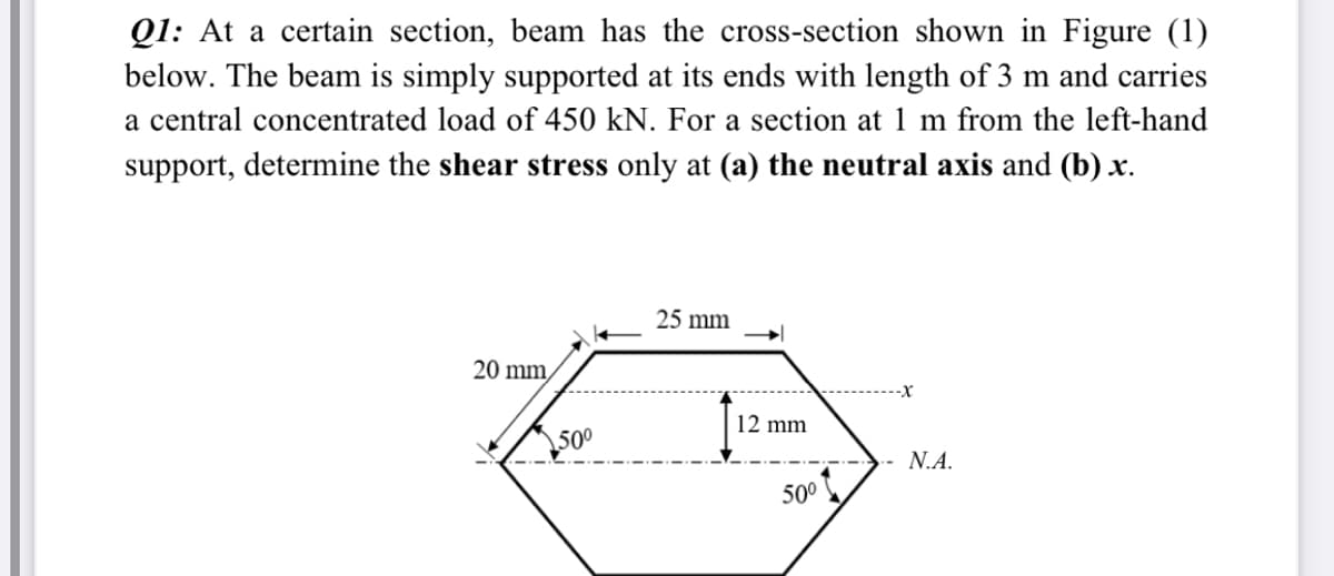
Transcribed Image Text:Q1: At a certain section, beam has the cross-section shown in Figure (1)
below. The beam is simply supported at its ends with length of 3 m and carries
a central concentrated load of 450 kN. For a section at 1 m from the left-hand
support, determine the shear stress only at (a) the neutral axis and (b) x.
25 mm
20 mm,
-X
12 mm
500
N.A.
50°
Expert Solution
This question has been solved!
Explore an expertly crafted, step-by-step solution for a thorough understanding of key concepts.

Step by step
Solved in 7 steps with 2 images

Knowledge Booster


Learn more about
Need a deep-dive on the concept behind this application? Look no further. Learn more about this topic, civil-engineering and related others by exploring similar questions and additional content below.Recommended textbooks for you