2.simple beam structure with roller placement at A and joint placement at B is loaded by external loads which can be seen in the figure below. P= 250 kN q= 20 kN/m M= 150 kN.m C D E 2 m 4 m 2.
Q: 100 kN 100 kN (4000 mm) (5000 mm) 75 kN D. (5000 mm) A 3 m (4000 mm) – 4 m E= 200 GPa Determine the…
A:
Q: A weight W= 120 kN is being supported by steel sections with force T, force F, and force C. The…
A: Given
Q: 2.5 m 1.5 m w = 5 kN/m MB = 2 kN.m A В
A:
Q: PROBLEM O1: For the cantilever beam loaded as shown in the figure. (1) Derive the expressions for…
A: The algebraic sum of the vertical forces at any section of a beam to the right or left of the…
Q: QUESTION 2 A continuous beam ABCD having a uniformly distributed load of 15 kN/m on span BC and…
A:
Q: Figure shows a rectangular beam section 10 cm wide and 20 cm deep. If the maximum flexural stress is…
A:
Q: 2. Determine the magnitude of the resultant of the two forces shown. F13 kN 30 5=7 kN
A:
Q: Analyze the following figure if: h=1.5 m, d=3.12 m, x-2.34 m What is the value of force in member…
A:
Q: Solve the following questions, show your solution and box your final answer. 1m. 1m. P SITUATION 1.…
A: Two types of forces involved in building any structure are tension and compression. Every material…
Q: PROBLEM 1. A simple beam loaded as shown. Determine the following: (1) reactions @ support; & (2)…
A:
Q: A simply supported beam of length 5m is subjected to the loading as shown below. Derive the…
A: Draw the free body diagram. Equilibrium of vertical forces,
Q: The hollow rectangular cross-sectioned beam (200 mm wide and 400 mm deep with 10 mm thickness) shown…
A:
Q: As shown in the figure, aluminum rod AB and steel rod BC, hinged to rigid supports, are pinned…
A:
Q: 2) The rigid bar is supported by two wooden posts and a spring as shown in the figure. If each of…
A:
Q: 20 1: a) A simply supported beam AB, 6 m long is loaded as shown in Figure 5 kN 2 kN 2 kN/m 1.5 m E…
A:
Q: The reaction RB for a overhanging beam as shown in figure is given as 5 kN/m 5 kN 2 kN D AT 2m. Im-…
A:
Q: A simply supported beam is loaded as shown in the figure. Determine the Ely value of the beam at…
A: Let,RA=vertical reaction at roller support in upward directionRB=vertical reaction at hinge support…
Q: A circular bar having 300 mm2 area is subjected to axial loads as shown in figure. Find the value of…
A: Elongation in bar is given by,∆=PLAEwhere,P=loading,L=length of bar,A=Area of cross section,E=…
Q: h₁ + 5.50m * 9.0m h₂
A:
Q: The two 4.6° wedges shown are used to adjust the position of the column under a vertical load F of…
A:
Q: Using MDM for the continuous beam below, determine the following structural parameters and support…
A:
Q: A weight W= 120 kN is being supported by steel sections with force T, force F, and force C. The…
A:
Q: Determine the horizontal and vertical component at A and B neglect the weight of the beam 1.5 m 4 kN…
A:
Q: The three-bar truss ABC shown in the figure has a span L = 3 m and is constructed of steel pipes…
A:
Q: 42 kN/m A B 6 m 8 m
A: let,RA=vertical reaction at support A in upward directionRB=vertical reaction at support B in upward…
Q: Determine the force P needed to pull the 50-kg roller over the smooth step. Take θ = 30°.
A: Determine the force 'p' needed to pull the 50-kg roller oversmooth step θ=30°
Q: For the beam loaded as shown below, compute the nodal displacements and member forces. El=constant.…
A:
Q: For the simply supported beam shown below, determine the internal resultant loadings at a point 0.5…
A:
Q: A reinforced concrete girder having a simple span of 8 m carries a uniform service dead load of 20…
A: Uniform service dead load= 20 kN/m Uniform service live load= 36 kN/m Width of beam=450 mm Depth of…
Q: 1.A hollow pipe with a mass of 3.5-kg is being lifted via crane at a height of s 3m. The lifting…
A:
Q: A weight W= 120 kN is being supported by steel sections with force T, force F, and force C. The…
A:
Q: Figure shows a truss structure subjected to two point loads. By using the stiffness method,…
A: Given : 3 members having AE/L = 1000 KN/m Stiffness method Static indeterminacy = 5-3 =2
Q: 2–31. The beam is subjected to the two concentrated loads as shown. Assuming that the foundation…
A: Figure is as shown
Q: A triangular plate with height 4 ft and a base of 6 ft is submerged vertically in water so that the…
A:
Q: The three-bar truss ABC shown in the figure has a span L = 3 m and is constructed of steel pipes…
A:
Q: A vertical rectangular gate weighs 6000 lbs and is 10 ft tall and 8 ft wide (into the paper). The…
A: From given data we can draw a free body diagram of gate as shown below:
Q: * 5 نقاط For the beam shown, if P = 12 kN and L = 3 m, then the value of the area under the bending…
A: The bending moment in the beam will be caused by the vertical component of the load The horizontal…
Q: Determine the member force CD (kN) shown in the figure. 3 KN 2 m 45° 130 30 2 m 2 m
A:
Q: Determine the magnitude of the vertical reaction force at D. Assume a = 5.0 ft, b = 10.0 ft, c =…
A: Free body diagram - Force in the vertical direction - ∑FY = 0⇒RB + RD - W×a+b - P = 0⇒RB + RD -…
Q: 10 kN В L. y 6 m 3 m D 3 m C A 60 kN
A:
Q: Consider the beam shown in (Figure 1). Suppose that w- 25 kN/m. Point E is just to the right of the…
A: Draw the free body diagram of section AB.
Q: 3) The overhanging beam supports the loads as shown in the figure. Determine the value Ely at point…
A: Given data EI = Constant
Q: 30 KN/m A B 3.00 m 6.00m H 5 Panels@4.00 m = 15.00 meters PROBLEM NUMBER 1: In the given cantilever…
A:
Q: Determine the bending stress (in Pa) at the top of the beam at point C for the beam shown below if P…
A: To Determine The bending stress (in Pa) at the top of the beam at point C for the beam shown
Q: Consider the beam shown in (Figure 1). EIEI is constant. Assume 2 and 3 are rollers. Take F = 38 kN
A: Consider the given data Consider the Fixed end moment m12=-wl8=-38×58=-23.75…
Q: From the figure shown, 10' kN H 3 m 20 kN 5 m 3 m 5 m В a. Determine the axial force of girder GH.…
A: Portal method will be used for this given question. Assumptions in portal method :- A) point of…
Q: Wedge Problem From the given figure, the mass of the block is 200kg. Coefficient of friction for all…
A: Equilibrium equations: Any forces acting on the body are calculated easily by applying the…
Q: Determine the Bar Forces and Type for the following members. Bar Member Magnitude , KN Type of Bar…
A: Given data:
Q: Q2: The force system, shown in figure (2), has a horizontal resultant (to the right) of 300 Ib (250…
A:
Q: A B C a b.
A:
2.1.Write the Equation and describe the style in the latitude of the structure
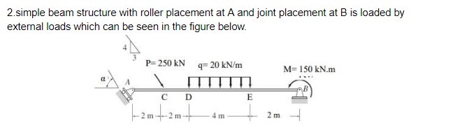
Step by step
Solved in 3 steps with 3 images
- For the beam and loading shown below, determine the beam deflection at point H. Assume that EI = 6.4 × 10⁴ kN·m2 is constant for the beam; w = 3.6 kN/m, LAB = 3.7 m, LBC = 7.4 m, LCH = 3.7 m.3.) For the given couple-force system shown, determine the horizontal component of Q. P= 335 KN Q= 44 KN R=74 KN-m Z=263 KNFor the beam and loading shown below, determine the beam deflection at point H. Assume that EI = 6.9 × 10⁴ kN·m2 is constant for the beam; w = 6.4 kN/m, LHA = 3.0 m, LAB = 6.0 m.
- A 7-m simple beam is carrying a uniform load of 25 kN/m over the entire beam with two-point loads of 15 kN at 1.5 m from both ends. If E = 200 Gpa and I = 0.000332 m^4, determine the following using the Double Integration Method: find a.) Midspan deflection b.) Deflection at 1.5 m from the left reaction.Two uniform loads of 112 kN/m acting downward are supported by a uniform upward pressure of q as shown in the figure.Determine support reaction at B . Given P=100 Kn L=10 m
- A couple M of moment 8 kN·m acting in a vertical plane is applied to a W200 * 19.3 rolled-steel beam as shown. Determine (a) the angle that the neutral axis forms with the horizontal plane, (b) the maxi-mum stress in the beamThe left half of the simply supported beam carries a uniformly distributed load of internsity 600N/m. A.Compute the value of ??? at midspan. B.If E= 10GPa, determine the smallest value of I that limits the midspan displacement to 1/360th of the span.The T-shaped beam shown above is supporting a concentrated load P at its free end. The beam has an allowable bending stress of ?????? = 250 MPa and an allowable shear stress of ?????? = 100 MPa. a) Determine the distance to the neutral axis (?̅), second moment of area (?), and the section modulus (?) of the cross-section.b) Draw the shear force diagram (SFD) and bending moment diagram (BMD) of the beam. On your diagrams, express the values of shear and moment in terms of the applied load P.c) Determine the maximum value of P such that bending failure will not occur.d) Determine the maximum value of P such that shear failure will not occur.e) Based on your answers to (c) and (d), what is the maximum load P that can be applied to the beam? Is this beam bending or shear governed?
- For the beam and loading shown below, determine the beam deflection at point H. Assume that EI = 5.6 × 10⁴ kN·m2 is constant for the beam; P = 40 kN, LAB = 3.9 m, LBH = 3.9 m.Refer to the beam loaded as shown. (a)What is the Value of horizontal reaction at the fixed support?(b)What is the value of resulting couple at A?A billboard 3m high by 4m wide is supported as shown in the figure. The totl weight of the billboard is 30 kN. H = 1.5 m and tetha= 60 degrees. Wimd pressure, q= 1.6 kpa Wind pressure coefficient = 1.0. Determine the reactions at the support.