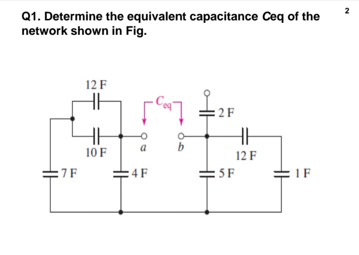
Q1. Determine the equivalent capacitance Ceq of the network shown in Fig. 12 F 2F a 10 F 12 F :7F :4F 5 F = 1 F


Q: Using the given circuit, calculate: 1) Equivalent capacitance 2) Charge across each capacitor 3)…
A: Solve the problem
Q: Q.3 Answer only Four of the following 1) If The AC Maxwell Inductance Capacitance Bridge has the…
A: Since you have posted multiple question , we will solve first question for you . If you want any…
Q: For the circuit shown below: determine i(t) of the circuit below, when v1(t)=10 cos 10t -Reactive…
A:
Q: Using the phase shift of 72º from the Experiment, determine the inductance value, L, of the inductor…
A:
Q: Capacitors C1 = 6.0 µF, C2 = 12 µF, and C3 = 5.0 µF are wired into the network below. a. Find the…
A: Use capacitor equivalent circuits Voltage same in parallel Currents same in series
Q: Find the equivalent inductance of the circuit shown in Fig. 6.31. Leg 4 H m m 8 H 7 H 20 H m m 10 H…
A: Given circuit,
Q: cion 8 For the circuit given below, determine the energy stored in 3 H inductor. 4 kfl 2H 16 V= 3 H
A: To solve above question, one should understand the behavior of Inductor and capacitor in DC circuit.…
Q: i. 247.32µF 18.42µF 74.38µF ii. iii. iv. 37.5µF 70 uF 4nF 100 μF 96 µF 200 μ 25 µF Ceq Compute the…
A:
Q: Short Problem: Given a parallel RLC circuit comprised of the following element: 57.81-ohm resistor,…
A:
Q: Answer the following questions: QI) For the circuit in Fig. (1), find the inductor voltage for t> 0.…
A: Here i have found the inductor voltage by differentiating the inductor current.
Q: Q1. Three inductances are connected as shown in Fig. What is the equivalent inductance? 0.1 H 0.3 H…
A: Solution !!
Q: Short Problem: Given a parallel RLC circuit comprised of the following element: 95.34-ohm resistor,…
A:
Q: The voltage across a 75 mH inductor is described by the equation νL = (25 V) cos(60t), where t is in…
A: Given: VL = (25 V) cos(60t) L = 75 mH SOL. a) at t = 0.1 s VL = (25 V) cos(60×0.1)VL = 24.86 V b)…
Q: For the circuit in Fig. below: b. Draw the phasor diagram of the voltages E, VR, and Vc. ll 30 N 0.2…
A:
Q: 2.00 μF C₂ + 90.0 V (a) Find the equivalent capacitance (in μF) of the system. 4.445 µF (b) Find the…
A:
Q: Given the following pairs of voltages and currents, indicate whether the element involved is a…
A: We know, The expression for voltage is given by,V=Vmsinωt ---(A)The expression for current is given…
Q: Q1:- A) Find the total capacitance CT shown in fig.1 if: i. the switch is open ii. the switch is…
A: According to the question we need to solve total capacitance CT at both conditions when the switch…
Q: (b) In the circuit of Fig. for Q. 5(b), determine the value of the capacitor C that will cause the…
A:
Q: Q1) For the circuit in Fig. (1), find the inductor voltage for t> 0. 1. 1. RI t=0 Fig. (1) ww
A:
Q: In the shown combination of capacitors, C=50 µF. Determine the equivalent capacitance between points…
A: Given: The circuit below shows the combination of capacitors with C=50 µF: To find: The equivalent…
Q: Q2. A 50 2 carbon resistor has two lead wires with inductance of 10 nH each. If the stray…
A: Given, R=50 ΩL1=10 nHL2=10 nHL=L1+L2=20 nHC=0.5 pF
Q: Q2. A 50 Q carbon resistor has two lead wires with inductance of 10 nH each. If the stray…
A: Impedance of inductor given byXL= jwL Impedance bof capacitor given by Xc= -j/wC
Q: What is the energy stored by the inductor in the circuit shown in Fig. 9.20 if R = 20 N? Ans. 667 mJ…
A: Given circuit is - Given values are - R=20Ohm
Q: 7. An ideal inductor, capacitor and resistor are connected in parallel across a 40 V a.c. supply.…
A: As per the guidelines of Bartleby we supposed to answer first three subparts of the question for…
Q: 50 μF 60 μΕ Ca 70 μ 20 μΕ 120 μF
A:
Q: Find the equivalent capacitance with respect to the terminals a, b for the circuit shown below 20 nF…
A: When two capacitors are in series, then the equivalent capacitance is 1cS=1C1+1C2 When two…
Q: A 397-Vrms, 60-Hz supply serves a load that is 10 kW (resistive), 5 kVAR (capacitive), and 15 kVAR…
A:
Q: 3 μF 6 μF 7 μF 0.2 μF | * CT b (a) SECTION 10.13 Capacitors in Series and Parallel 44. Find the…
A:
Q: A 1kQ resistor, a 5mH ideal inductor, and a 1nF capacitor are connected in parallel. Find the total…
A:
Q: For the circuit in Fig. below: b. Draw the phasor diagram of the voltages E, VR, and Vc. 30 Ω 0.2 H…
A:
Q: For the given circuit LT (Total Inductance) = 2.25 H, Determine Lx. 3 H 7 H 3H 3H LT= 2.25 H For the…
A:
Q: Q) Consider the circuit shown in Fig.1. The input to the circuit is the voltage source v(t)=7.68cos…
A: Given Input voltage and output voltage.we need to determine capacitance. Please find the below…
Q: ure inductance of L = 144 mH 118 V, 50 Hz supply. The cure ctor is given by
A:
Q: Establish the general equation H(ω) = Vo/Vi for the ratio between the voltage across the capacitor C…
A:
Q: Capacitance by AC- Bridge: In AC Bridge experiment, the balance was obtained as shown. Therefore,…
A: In this answer we will find the value of Cx for the bridge balance condition as shown below.
Q: Q1/ Determine the value of the capacitance, C for the circuit shown in Fig.(1) The network function…
A: The circuit is shown below: The output voltage is given the voltage division rule,…
Q: A parallel-plate capacitor whose plates have area of 30 cm2 and 5 mm apart contains a medium with…
A: Given; A parallel-plate capacitor having A=30 cm2d=5 mmεr=3
Q: Obtain the inductor current for both t0 in each of the circuits in Fig. 12 Q 2 A 42 1=0 3.5 H (a) 24…
A: Transient response is the response of a system which is the change in transient(equilibrium) or…
Q: Q1) For the circuit in Fig. (1), find the inductor voltage for t>0. 1, R1 R: t=0 Fig. (1) le ww
A: as per our guidelines we are supposed to answer only one question. Kindly repost other questions as…
Q: Given the circuit shown below, determine the voltage across the capacitor 60 0.25 F HH + Vcdt) 3…
A:
Q: Consider the circuit in Fig. Under dc conditions, find: the energy stored in the inductor 20 12 v (+…
A: At steady state capacitor acts as open circuit and inductor acts as short circuit. So at stedy…
Q: Q1. Determine the equivalent capacitance Ceq of the network shown in Fig. 12 F =2F a b 10 F 12 F :7F…
A:
Q: * Compute the equivalent capacitance Ceq as labeled in Fig. HE 2 F 7 F 4 F 8 F Cea 5 F 12 F 5 F 1 F…
A: Find below detailed solution with answers in box at the end
Q: Problem 2: Given this network of capacitors: C2 C1 4 uF 1 uF C3 3 uF C4 2 uf C5 2 uF Assuming the…
A: Equivalent capacitance: This is the total capacitance of the capacitors in the circuit. Calculation…
Q: SECTION 11 Inductors in Series and in Parallel as. Reduce the network in Fig. 103 to the fewest…
A:
Q: Problem 2: Given this network of capacitors: c2 4 uF 1 uF C3 3 uF C4 2 uf C5 2 uF Assuming the…
A:
Q: 20 L + t = 0 60 V 31.25 µF vo350 mH R = 20 N, L = 50 mH, C = 31,25 µF Constant voltage source Vs(t)…
A: In the circuit, Initial switch is open, after a long time capacitor act as open circuit. Switch…
Q: Question 1 C= 2nF C= 3nF C,= 6nF C,= 4nF C- SnF V= 24V C= 2nF C= 2nF Using the given circuit,…
A:
Q: -100/100V 50k B.O.V=25V 0.1k 50 H 50k For the circuit shown, at what angle the Triac starts to…
A: for the circuit shown in the figure at what angle the Traic starts to conduct in positive half cycle…
Q: Cime (s) 0.5 1 1.5 2 2.5 3 3.5 4 Joltage (V) | 100 62 38 21 13 7 4 2 3
A:


Trending now
This is a popular solution!

Step by step
Solved in 2 steps with 3 images


- Find the impedance theoretically of a wire if it carries the frequency 10 kHz have a voltage is 8v, the current is 2mA, resistance is 12 kΩ , inductance 27 mH and capacitance 0.2 µfFind the circuit resistance and inductance if the current flowing through the RLC circuit is two milliamps. The capacitance is twenty microfarad and the applied voltage is three volts at a frequency of two hundred fifty kilo hertz. Answer: 20.264 nH, 1.5 K ohmUsing the phase shift of 72º from the Experiment, determine the inductance value, L, of the inductor shown. Vr(t) =3.7272 cos(4000 t - 72°) [V]
- A 200-Ω resistor is connected in series with a 1.32-uF capacitor. The voltage across the resistor is vR = (1.20 V) cos (3415.59 rad/s)t. Determine the capacitive reactance of the capacitor.Given the capacitance of four capacitors Ca= 30 µF, Cb = 20 µF, Cc = 40 µF and Cd = 10 µF. If Cb and Cc are connected in parallel and the parallel combination is connected in series with Ca and the combination is further connected in parallel with Cd, calculate (a) the equivalent capacitance (b) the voltage across each capacitor if the circuit is supplied by 240 volts DC source (c) the charge on each capacitor.A resistance of 10 ohm, an inductor of 300 mH and a capacitor of 50 uF are connected in series. If the AC voltage supplied to the connection is given by v = 300 sin (2 π 50 t + 30), write the equation for the current.
- The voltage across a 75 mH inductor is described by the equation νL = (25 V) cos(60t), where t is in seconds.a. What is the voltage across the inductor at t = 0.10 s?b. What is the inductive reactance?c. What is the peak current?a. find the total capacitance of the circuitb. tind the charge (Q) acting on the circuitThe capacitor of external defibrillator must be loaded at 1500V, in order to generate a two-phase wave of 150 J.Considering a transthoracic impedance is 80ohms and a capacitance of 30 000 uF. 3- What is the energy of the capacitor?4- What is the internal impedance of the defibrillator in the previous cases?
- Show that at a given frequency ω, the circuits will have the same impedance between the terminals a,b ifR1=R21+ω2R22C22,C1=1+ω2R22C22ω2R22C2.2. Find the values of resistance and capacitance that when connectedin series will have the same impedance at 40 krad/s as that of a1000 Ω resistor connected in parallel with a 50 nF capacitor.a series r-c circuit takes a current whose equation is i=0.85sin(754t+pi/4) when connected to a source of emf having the equation e=340sin754t. calculate the capacitance of the capacitor, circuit power factor, and power.Short Problem: Given a parallel RLC circuit comprised of the following element: 57.81-ohm resistor, ideal inductor with reactance of 65.75 ohms; and a capacitor with reactance of 6.59 ohms. Compute for true power in watts given an ac voltage source of 100 cis 0 volts.