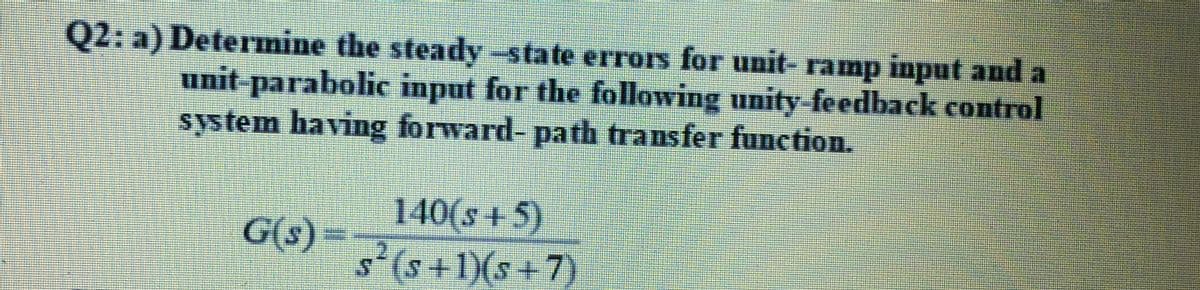
Q2: a) Determine the steady-state errors for unit- ramp input and a unit-parabolic input for the following unity-feedback control system having forward- path transfer function. 140(s+5) G(s) = s'(s+1)(s+7)
Q: Control system A/ Define following :- transfer function, transient response, and the type of the…
A:
Q: 4. A single-loop negative feedback system has the loop transfer equation: L(s) = Ge(s)G(s) = K(s +…
A: GIVEN: L(s)=Gc(s)G(s) =K(s+2)2(s(s2+1)(s+8)) FIND: (1) sketch…
Q: CP4.1 Consider a unity feedback system with 12 G(s) || s2 + 2s + 10 Obtain the step response and…
A:
Q: 3) A plant with the given transfer functoin Gp(s) is going to be controlled by a P-controller of…
A: The solution is given below
Q: Q3: A unity feedback control system is characterized by the open loop transfer function G(s)=…
A: When a system is disturbed from its original state and comes back to its original state, then it is…
Q: Q.5 (a) Using the Routh-Hurwitz crition, determine if the following systems are stable or unstable,…
A:
Q: A system is to be analyzed using s-domain analysis. а. Construct the root locus for a unity-feedback…
A:
Q: 2. A system has an open-loop transfer function given by s2 + 6s + 18 G(s) 82 along with a negative…
A: Hello. Since your question has multiple sub-parts, we will solve first three sub-parts for you. If…
Q: 5.22 Consider a feedback system with a plant model (8 – 1)(s – 3) (8 – 2)(s+ 1)²' Use the root-locus…
A: Controller: It is used to reduce the difference between real value and desired value. This is the…
Q: 3. A dynamic system with the following feedback architecture will be controlled by selecting…
A: The forward path gain and feedback gain of a negative feedback closed system are Gs=Ka2s2+KaKh+1s,…
Q: 6. Model the following control system and find its time response according to these specifications:…
A: Transfer function-The transfer function is the ratio of the Laplace transform of output to Laplace…
Q: Q4: For the system G(s) it is intended to set the location of the dominant closed loop poles at %3D…
A: The problem is about the steady-state response improvement, so need to design LAG compensator for…
Q: ity feedback system, find the value of K such that closed-loop a pole at real axis = -5 K(s+1) G(s)…
A:
Q: Figure (1) represents a position control system. Assume K = 0 and find the damping ratio of the…
A: When Kt=0 and the amplifier gain is equal to 5, then the corresponding block diagram becomes The…
Q: A closed loop system with unity feedback and having the forward loop transfer function as 14.4 G(s)…
A: Given; The forward transfer function is Gs=14.4ss+0.1s And the feedback is unity i.e. Hs=1
Q: E5.4 A feedback system with negative unity feedback has a loop transfer function 2(s + 8) s(s + 4)…
A: The open-loop transfer function of a system with negative unity feedback is given as…
Q: In the feedback system given below; G1(s) = 5*K, G2 (s)= 1/s(s+4*4), H(s)= 1 given as time to…
A:
Q: A unity feedback system with forward transfer of: G(s): (s² + 6S + 18) The system should be operated…
A: Part (1): Consider the open-loop transfer function,
Q: Q3 (a) Consider the transfer function system below. Y(s) s2 + 4s + 6 U(s) s3 + 6s2 + 4s + 2 Obtain a…
A:
Q: Exercise Introduction •Root locus is a graphical method in which roots of the characteristic…
A: Here, No. of poles (p) = 3 No. of zeroes (z) = 0 p-z = 3-0…
Q: Express the signal x(t) shown in the figure below using basic functions (Unit-impulse, Unit-step,…
A: To express the signal x(t) shown in the figure below using basic functions, For the signal given…
Q: Consider the feedback system below for which we want to design a controller K neeting some stability…
A:
Q: For the unity feedback system as shown below where 450(s + 8)(s + 12)(s+ 15) G(s) = %3D s(s + 38)(s²…
A:
Q: 2: a) Determine the steady-state error for three step input for the following unity-feedback control…
A:
Q: Q1/A For the following systems, are the response of these systems under damping, over damping, or…
A: Since we are authorized to answer only 1 queation at a time so i am answering only 1st please repost…
Q: Q4: For the system G(s) = it is intended to set the location of the dominant closed loop poles at…
A: (1) Steady state error is improved when we add Proportional Integral (PI) Controller in forward…
Q: A block diagram for a feedback control system subjected to a unit step input is shown in Figure Q2…
A:
Q: Q5. A regulating system controls a process which has a transfer function s+ 10 Gp(s) = s (s + 15) A…
A: A) Gp(s)=s+10s(s+15)Gc(s)=K1(s+10)Root locus:after the pole-zero calculation, the open loop transfer…
Q: Discussion: (a) Construct the root-locus diagram for the unity feedback control system for which the…
A: "According to the Company's policy we will solve the first three subparts of the question". We need…
Q: A plant has the open loop transfer function shown below, with unity negative feedback and step input…
A:
Q: 23 The block diagram in figure Q3 shows a plant G, (s) controlled by a controller G.(s) using a…
A:
Q: We are given a system's transfer function as 4 T(s) = s2 – 4 Construct a state-space model for the…
A:
Q: Consider unity negative feedback applied to the system: G(s) = k/s(s^2+4s+5) (a) Give a complete…
A:
Q: For a unity feedback configuration, where; K(s +3s +30) G(s) = $"(s+5) is to have 1/6000 error…
A:
Q: For a unity feedback system where 5000 G(s) = s2(s + 25) a. What is the expected percent overshoot…
A:
Q: In the unit feedback system given below, G(S), K(s+b) G(s): %3D s(sta) is given as. 2% of the…
A:
Q: Problem 1 yla) 2-1 (a) Find the impulse response of the causal system given above (b) When the input…
A: a) Three unit delays are shown in the above diagram.
Q: A feedback system is depicted below in which C(s) is the controller and P(s) is the plant. The…
A:
Q: a : Obtain the Unit-step response of a unity-feedback whose open-loop transfer function is…
A:
Q: 5. The following forward-path transfer functions are given for a single-loop unity-feedback control…
A:
Q: Problems for home work(time domain response) Q4) A particular control system yielded a steady state…
A:
Q: 2000 Gp (s) (s + 20)(s+ 100) The gain-compensated system operates with a damping ratio of 0.8.…
A: Note: We are authorized to answer one question at a time, since you have not mentioned which…
Q: Electrical Engineering For a unit feedback system having the following gain functions: G(s) Ks -…
A: Given: For a unity feedback system having the following gain functions: Gs=Ks-4.21s22s+5.7 To find:…
Q: 2. A system is to be analyzed using s-domain analysis. а. Construct the root locus for a…
A:
Q: A plant has the open loop transfer function shown below, with unity negative feedback and step…
A: A control system is a combination of elements arranged in a planned manner wherein each element…
Q: My Figure 1 The system shown in Figure 1 simulates two masses. The mass of the engine and the car…
A: In this circuit, we need to draw the free body diagram and differential equation. If all initial…
Q: Common Data for Q2, Q3, Q4: For a unity feedback system, we have the forward path transfer function:…
A:
Q: R(s)- K G(s) -Y(s) Figure 2: A series proportional controller with gain K enclosed within a unity…
A:
Q: The unitary negative feedback system below is asymptotically stable, for as? + 1 G(s) = - with =5.5,…
A: Given G(s)=as2+1(bs+1)3 with b =5.5
Q: ven the shown circuit and its feedback block diagram, find the transfer function in the block B2.…
A: By kcl at ouput node I(s) = Vo/(sL) + Vo/(R)
Step by step
Solved in 3 steps
- The upper critical frequency of an op-amp’s open-loop response is 200 Hz. If the midrange gain is 175,000, answer the following: What is the ideal gain at 200 Hz? What is the actual gain? What is the op-amp’s open-loop bandwidth?The open-loop gain A of real (nonideal) op-amps isvery large at low frequencies but decreases markedlyas frequency increases. As a result, the closed-loopgain of op-amp circuits can be strongly dependent on frequency. Determine the relationship between a finiteand frequency-dependent open-loop gain AV(OL)(ω)and the closed-loop gain AV(CL)(ω) of an invertingamplifier as a function of frequency. Plot AV(CL)versus ω. Notice that −RF/RS is the low-frequencyclosed-loop gain.Find the closed-loop transconductance, input resistance, and output resistance for the series-series feedback amplifier as shown if the op amp has an open-loop gain of 80 dB, an input resistance of 25kΩ , and an output resistance of 1kΩ. Assume the amplifier is driven by a signal voltage with a 10-kΩ source resistance, and the feedback network is implemented with R2=91kΩ and R1=10kΩ.
- For the open-loop system G(s) = 3/s^2 + 2s - 3 assume there is a feedback with a proportional gain, K. And sketch a locus of closed-loop rootsverse K. What is the minimum value of K to achievea stable system?below is the representation of a linear control system in the state space.a) examine the controllability and observability of this systemb) estimate the unit digit response by finding the current eigenvalues of this systemC) find the feedback Matrix K= (k1 k2) that must be applied so that the system can be a two - layer root in-2A unity-feedback system has forward transfer function (see attached). a) Sketch the root locus for this system as K varies from 0 to ∞; b) Use the Routh-Hurwitz test to determine the range of K for the system to be stable; show this value of K on the root locus plot.
- An uncompensated unity feedback system with certain deficiencies has no zeroes and poles at -1, -2 and -5. Answer the following questions based on the above description of the system Determine using an apt technique, the gain of the system at damping ratio 0.45Consider the unity-feedback control system with the following feedforward transfer function: G(s) = K / s(s2+4s+5) (1) Plot the root locus. (2) Determine closed-loop poles that have the damping ratio of 0.5. Find the gain value K at this point. (3) For what value of K is the overshoot less than 10% and the maximum rise time less than 1.5s.a) Design an inverting amplifier with a gain of 4. Use an ideal op amp, a 30 kohm resistor in the feedback path, and +-12 v power supplies. b) Using your design from part a, determine the range of input voltages that will keep the op amp in it's linear operating region. c) suppose you wish to amplify a 2 V signal, using your design from part a, with a variable feedback resistor. What is the largest value of feedback resistance that keeps the op amp in its linear operation region? Using this resistor value, what is the new gain of the inverting amplifier?
- Feedback Control 2. Consider the unit-step response of unity-feedback control system whose open-loop transfer function is ?Given a unity feedback system with G (s) =K/ s (s+4). What is the value of K for a damping ratio of 0.5?1. Design an inverting amplifier with a gain of 4. Use an ideal op amp, a 30 kΩ resistor in the feedback path, and ±12 V power supplies. 2. Using your design from part (a), determine the range of input voltages that will keep the op amp in its linear operating region. 3. Suppose you wish to amplify a 2 V signal, using your design from part (a) with a variable feedback resistor. What is the largest value of feedback resistance that keeps the op amp in its linear operation region? Using this resistor value, what is the new gain of the inverting amplifier?