Q2/ A) Draw the logic circuit for each of the following: 1) The operations (1101 -1010) and (1101 + 1010) 2) 1-4 DEMUX, then draw the output waveforms if the input is: Dn = 10011101, So = 11100110, Si = 10010100 3) The expression ( (Y + Z)(XY +Z) X) by using NOR gate only.
Q2/ A) Draw the logic circuit for each of the following: 1) The operations (1101 -1010) and (1101 + 1010) 2) 1-4 DEMUX, then draw the output waveforms if the input is: Dn = 10011101, So = 11100110, Si = 10010100 3) The expression ( (Y + Z)(XY +Z) X) by using NOR gate only.

Chapter22: Sequence Control
Section: Chapter Questions
Problem 6SQ: Draw a symbol for a solid-state logic element AND.

Related questions
Question
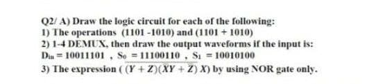
Transcribed Image Text:Q2/ A) Draw the logic circuit for each of the following:
1) The operations (1101 -1010) and (1101 + 1010)
2) 1-4 DEMUX, then draw the output waveforms if the input is:
Din = 10011101, So = 11100110, Si = 10010100
3) The expression ( (Y + Z)(XY + Z) X) by using NOR gate only.
Expert Solution
This question has been solved!
Explore an expertly crafted, step-by-step solution for a thorough understanding of key concepts.

Step by step
Solved in 3 steps with 3 images

Knowledge Booster


Learn more about
Need a deep-dive on the concept behind this application? Look no further. Learn more about this topic, electrical-engineering and related others by exploring similar questions and additional content below.Recommended textbooks for you