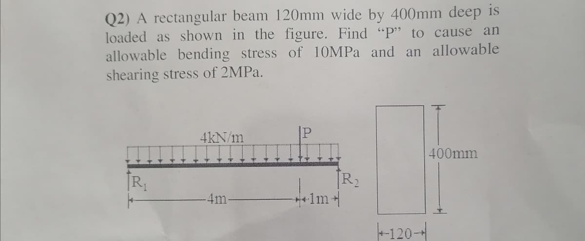
Q2) A rectangular beam 120mm wide by 400mm deep is loaded as shown in the figure. Find "P" to cause an allowable bending stress of 10MPA and an allowable shearing stress of 2MPA. 4kN/m 400mm R2 1m+ 4m -120-
Q: A hollow steel box beam has the rectangularcross section shown in the figure. Determinethe maximum…
A: Given Allowable shear stress = 36 MPa To find Allowable shear force
Q: A wood beam carries the loading shown in the figure. Calculate the magnitude of the bending stress…
A:
Q: A wood beam carries the loading shown in the figure calculate the magnitude of the bending stress…
A:
Q: 1. Draw shear force and bending moment diagrams for the beam shown in figure. 30kN 2m Hello, Mr., tw…
A:
Q: 5 m 5 m 2m 2 m 12 kN 4 kN 20 C 12 -20 12 -4 kN Shear Diagram 1. Add file LLI
A: Load Diagram and BMD
Q: a B * W - b P cl C 커다 h
A:
Q: A wood beam carries the loading shown in the figure. Calculate the magnitude of the bending stress…
A:
Q: Q1) A beam has a loadingsystem as shownin the figure below. (1) draw the shear diagam (2) m om ent…
A: Solution: Note: Dear Student! As per our guidelines, we are only allowed to answer a single…
Q: A solid rectangular homogeneous section (total length = 7.2m) is simply supported, where b = 50 mm…
A: Draw the schematic diagram of the beam representing the forces.
Q: The vertical shear force acting in a beam with the cross section shown in the figure is 20 kips.…
A:
Q: A vertical loads of 400 N acts at the end of a horizontal rectangular cantilever beam 2 m long and…
A:
Q: 1. Simulate for the maximum shear stress and strain on a beam as shown in figure below. 75 N 125 N-m…
A:
Q: Determine the internal shear and moment acting at a section passing through point C n the beam shown…
A: Solution: Area of under the loading diagram gives the total load acting on the beam and the position…
Q: For the simply supported beam subjected to the loading shown, sketch the shear force diagram.…
A:
Q: Q1) A simply supported beam having a length of 7 meters carries a uniformly distributed load of…
A: Any action that can change the state of motion is called force, Force is described by its magnitude,…
Q: Q: Find the value of W which can be applied to the beam shown in figure below. if the maximum…
A:
Q: In the simple beam given in the figure, Find the maximum slope and depression using the values…
A: When any beam is subjected to a load, it deflects, and the neutral axis becomes a curved line which…
Q: A wood beam carries the loading shown in the figure. calculate the magnitude of the bending stress…
A:
Q: Ex 2 praw i shear force and bending Axial force moment diagram ? 125 KN 200 KN AX 2m By
A: Consider the free body diagram shown below for the given beam.
Q: A wood beam carries the loading shown in the figure, calculate the magnitude of the bending stress…
A:
Q: 60 KN 20 kN/m 40 kN B -2m-2m-2 m-4m- 50 kN E 50 mm 120 mm L 120 mm T 50 mm
A:
Q: gomm S.3 20 EN 20EN 30 mm A 3m |30mng b0 mm b. 30 mm 50mm A beam AB, made of three boiled boards, is…
A: Given:
Q: A wood beam carries the loading shown in the figure. calculate the magnitude of the bending stress…
A:
Q: From the given beam shown below, find the shear value at segment BC (VBC). 20kN 40KN 65kN/m ↓↓ Ţ A k…
A:
Q: A rectangular beam of 100 mm wide is subjected to maximum shear force of 50 kN, the corresponding…
A: Given data , w= 100 mm. τmax=3 N/mm2 Vmax= 50 KN= 50000 N Let b= depth
Q: Q1) A simply supported beam is 3 m long and carries a vertical load of 5 kN at point 1m from the…
A: first finding reaction force RA+RB=5kn clockwise +vetaking moment aboit…
Q: Q/ The figure shows the vertical cross- section of a beam which at this section is subjected to a…
A:
Q: Cross section of a beam is shown in Figure 3. If a shear force V=100 kN is applied to the beam, find…
A:
Q: Q: Find the value of W which can be applied to the beam shown in figure below. if the maximum…
A: Consider the reaction at the supports RB and the reaction at supports C is Rc. Moment about C,…
Q: The beam given in the figure below is subjected to the uniform distributed load of w=50 kN/m. (a)…
A:
Q: A wood beam carries the loading shown in the figure. calculate the magnitude of the bending stress…
A:
Q: A simply supported beam carries a distributed load of 10 kN/m over a span of 5 m and a concentrated…
A: Given Data: udl intensity w=10 KN/m Span L=5 m Point loads =10 KN ,8 KN
Q: $D aluminum steel t A composite beam is a built-up section made of aluminium and reinforced with a…
A:
Q: Q2/Draw the Shear Diagram and Moment Diagram for figure below 30 kN/m A 3 m 2m 1m> 20 KN B 40 KN
A: To draw SFD and BMD
Q: 120 KN 100 mm H 400 mm B 22m 150 mm Find the shear stress at point H on the beam. The wall thickness…
A:
Q: In the simple beam given in the figure, Find the maximum slope and depression using the values.…
A: The bending moment is a reaction in a structural element that is subjected to an external force or…
Q: Find the cross sectional dimensions of the smallest square beam that can be loaded as shown in the…
A: Given: Load acting in downward direction at 4 m away from the left end A→P=12 KN And moment applied…
Q: A wide flange beam as shown below is subjected to a shear force V. Using the dimensions of the cross…
A:
Q: Q13: In the figure, the (a , ) bending stress equal ---- if the moment inertia 5 m and the…
A:
Q: From the given figure below, determine the minimum width of the beam if the flexural stress is not…
A: The minimum width of the beam: bmin = 231.11 mm
Q: Q2, For the composite section beam shown in figure below. Determine the maximum bending stresses.…
A: N = ratio of Elastic modulii= Esteel /Ewood = 10 we will now develop the equivalent beam
Q: Two planks are nailed together to form the T-beam shown 50 mm 300 mm in the figure. Each nail can…
A: Given: The allowable shear stress of wood material is τa=3 MPa=3 N/mm2, The shear force that each…
Q: Consider the given figure. Given: P= 4.6 kips. 4 kips 5 kip-ft C D В A - 5 ft 5 ft→5 ft→| Determine…
A: To Find: Vmax Mmax
Q: is three times larger than in steel shaft. Q1) For the section shown aside, if the bending stress at…
A:
Q: A wood beam carries the loading shown in the figure. calculate the magnitude of the bending stress…
A: calculate the magnitude of the bending stress (in Pa) at a point 23 mm from the top of the beam on a…
Q: Box beam in the figure is made of four pieces of wood nailed to each other as shown. has been made.…
A: Given that, Maximum allowable vertical shear in the beam, F=180a=18,b=16,c=2a=36,d=5b=80, Maximum…
Q: 6 kN/m Since the bending safety stress *em = 10 MPa, shear safety stress em = 600 kPa of the…
A: Draw a diagram for the beam. Here, RA and RC are the support reactions as shown in the figure.…
Q: Q3) s) For a beam with a cross section of equilateral triangle of side length a = 20 mm, (a) draw…
A: The free body diagram of the beam is given below, on taking moment about B,…
Trending now
This is a popular solution!
Step by step
Solved in 7 steps
- Two identical, simply supported beams AB and CD are placed so that they cross each other at their midpoints (sec figure). Before the uniform load is applied, the beams just touch each other at the crossing point. Determine the maximum bending moments (mab)max* and (MCD)max beams AB and CD, respectively, due to the uniform load if the intensity of the load is q = 6.4 kN/m and the length of each beam is L = 4 m.A rectangular beam with semicircular notches, as shown in part b of the figure, has dimensions h = 120 mm and h1= 100 mm. The maximum allowable bending stress in the plastic beam is emix = 6 M Pa, and the bending moment is M = 150 N · m. Determine the minimum permissible width bminof the beam.The cross section of a rectangular beam having a width b and height h is shown in part a of the figure. For reasons unknown to the beam designer, it is planned to add structural projections of width b/9 and height d/9 the top and bottom of the beam (see part b of the figure). For what values of d is the bending-moment capacity of the beam increased? For what values is it decreased?
- The cross section of a sand wie h beam consisting of aluminum alloy faces and a foam core is shown in the figure. The width b of the beam is 8.0 in, the thickness I of the faces is 0.25 in., and the height hcof the core is 5.5 in. (total height h = 6.0 in). The moduli of elasticity are 10.5 × 10⁶ psi for the aluminum faces and 12.000 psi for the foam core. A bending moment M = 40 kip-in. acts about the z axis. Determine the maximum stresses in the faces and the core using (a) the general theory for composite beams and (b) the approximate theory for sandwich beams.A rectangular beam with notches and a hole (see figure) has dimensions h = 5.5 in., h1= 5 in., and width b = 1.6 in. The beam is subjected to a bending moment M = 130 kip-in., and the maximum allowable bending stress in the material (steel) is emax = 42,000 psi. What is the smallest radius Rminthat should be used in the notches? What is the diameter dmixof the largest hole that should be drilled at the mid height of the beam?A simple beam A B of a span length L = 24 ft is subjected to two wheel loads acting at a distance d = 5 ft apart (see figure). Each wheel transmits a load P = 3.0 kips, and the carriage may occupy any position on the beam. Determine the maximum bending stress Gmaxdue to the wheel loads if the beam is an I-beam having section modulus S = 16.2 in3. If d = 5 ft. Find the required span length L to reduce the maximum stress in part (a) to 18 ksi. If L = 24 ft, Find the required wheel spacing s to reduce the maximum stress in part (a) to 18 ksi.
- The cross section of an unbalanced wide-flange beam is shown in the figure. Derive the following formula for the distance /h from the centerline of one flange to the shear center S: h1t2b23ht1b13+t2b23 Also, check the formula for the special cases of a T-beam (b2= t2=0) and a balanced wide-flange beam (t2= ttand b2= ty).A hollow box beam with height h = 16 in,, width h = 8 in,, and constant wall thickness r = 0.75 LiL is shown in the figure. The beam is constructed of steel with yield stress ty = 32 ksi. Determine the yield moment My, plastic moment A/p, and shape factor.A beam supporting a uniform load of intensity q throughout its length rests on pistons at points A, C and B (sec figure). The cylinders are filled with oil and are connected by a tube so that the oil pressure on each piston is the same. The pistons at A and B have diameter d1and the piston at C has diameter D2. (a) Determine the ratio of d2to d1so that the largest bending moment in the beam is as small as possible. Under these optimum conditions, what is the largest bending moment Mmaxin the beam? What is the difference in elevation between point C and the end supports?
- The hollow box beam shown in the figure is subjected to a bending moment M of such magnitude that the flanges yield but the webs remain linearly elastic. (a) Calculate the magnitude of the moment M if the dimensions of the cross section are A = 15 in., A] = 12.75 in., h = 9 in., and ey =7.5 in. Also, the yield stress is eY = 33 ksi. (b) What percent of the moment M is produced by the elastic core?Find expressions for shear force V and moment M at v = L/2 of beam AB in structure (a). Express V and M in terms of peak load intensity q0and beam length variable L. Repeat for structure (b) but find Fand M at m id-span of member BC.A tapered cantilever beam AB supports a concentrated load P at the free end (see figure). The cross sections of the beam are rectangular tubes with constant width b, outer Tube depth dAat A, and outer tube depth dB— ldA/2 at support B. The tube thickness is constant, as t = dA/20. IAis the moment of inertia of the outer tube at end A of the beam. If the moment of inertia of the tube is approximated as la{x) as defined, find the equation of the deflection curve and the deflection 5^ at the free end of the beam due to the load P.