Q: Find the value of W which can be applied to the beam shown in figure below. if the maximum bending stress is 20 MPa and the maximum shearing stress is 2 MPa.
Q: Find the value of W which can be applied to the beam shown in figure below. if the maximum bending stress is 20 MPa and the maximum shearing stress is 2 MPa.

Mechanics of Materials (MindTap Course List)
9th Edition
ISBN:9781337093347
Author:Barry J. Goodno, James M. Gere
Publisher:Barry J. Goodno, James M. Gere
Chapter6: Stresses In Beams (advanced Topics)
Section: Chapter Questions
Problem 6.9.3P: The cross section of an unbalanced wide-flange beam is shown in the figure. Derive the following...

Related questions

Question
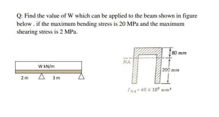
Transcribed Image Text:Q: Find the value of W which can be applied to the beam shown in figure
below . if the maximum bending stress is 20 MPa and the maximum
shearing stress is 2 MPa.
80 mm
NA
W KN/m
200 mm
2 m
3 m
INA 40 x 105 mm
Expert Solution
This question has been solved!
Explore an expertly crafted, step-by-step solution for a thorough understanding of key concepts.

Step by step
Solved in 2 steps with 2 images

Knowledge Booster


Learn more about
Need a deep-dive on the concept behind this application? Look no further. Learn more about this topic, mechanical-engineering and related others by exploring similar questions and additional content below.Recommended textbooks for you
Mechanics of Materials (MindTap Course List)
Mechanical Engineering
ISBN:
9781337093347
Author:
Barry J. Goodno, James M. Gere
Publisher:
Cengage Learning
Mechanics of Materials (MindTap Course List)
Mechanical Engineering
ISBN:
9781337093347
Author:
Barry J. Goodno, James M. Gere
Publisher:
Cengage Learning