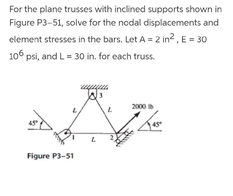
For the plane trusses with inclined supports shown in Figure P3-51, solve for the nodal displacements and element stresses in the bars. Let A = 2 in2 , E = 30 106 psi, and L = 30 in. for each truss. 3 2000 lb L. 45° 45° L. Figure P3-51
For the plane trusses with inclined supports shown in Figure P3-51, solve for the nodal displacements and element stresses in the bars. Let A = 2 in2 , E = 30 106 psi, and L = 30 in. for each truss. 3 2000 lb L. 45° 45° L. Figure P3-51

Mechanics of Materials (MindTap Course List)
9th Edition
ISBN:9781337093347
Author:Barry J. Goodno, James M. Gere
Publisher:Barry J. Goodno, James M. Gere
Chapter7: Analysis Of Stress And Strain
Section: Chapter Questions
Problem 7.3.14P: The state of stress on an element along the hydraulic lift cylinder on a truck is trv= — 5 MPaLFind...

Related questions
Question
Transcribed Image Text:For the plane trusses with inclined supports shown in
Figure P3-51, solve for the nodal displacements and
element stresses in the bars. Let A = 2 in2, E = 30
106 psi, and L = 30 in. for each truss.
mmm.
W3
2000 Ib
45°
45°
1.
L
Figure P3-51
Expert Solution
This question has been solved!
Explore an expertly crafted, step-by-step solution for a thorough understanding of key concepts.

This is a popular solution!

Trending now
This is a popular solution!

Step by step
Solved in 4 steps with 4 images

Knowledge Booster


Learn more about
Need a deep-dive on the concept behind this application? Look no further. Learn more about this topic, mechanical-engineering and related others by exploring similar questions and additional content below.Recommended textbooks for you
Mechanics of Materials (MindTap Course List)
Mechanical Engineering
ISBN:
9781337093347
Author:
Barry J. Goodno, James M. Gere
Publisher:
Cengage Learning
Mechanics of Materials (MindTap Course List)
Mechanical Engineering
ISBN:
9781337093347
Author:
Barry J. Goodno, James M. Gere
Publisher:
Cengage Learning