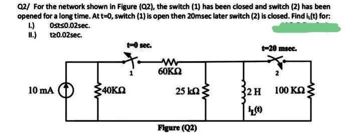
Q2/ For the network shown in Figure (02), the switch (1) has been closed and switch (2) has been opened for a long time. At t-0, switch (1) is open then 20msec later switch (2) is closed. Find i(t) for: 1.) Osts0.02sec. I1.) 120.02sec. -O sec. t-20 msec. 60KO 10 mA 40KO 25 kn 2 H 100 KO Figure (Q2)
Q: Find the voltage at node P in the figure shown.
A: The given circuit is shown below:
Q: For the DC circuit shown in Figure P30, find the voltage across each resistor and the current in…
A: We have to calculate the voltage and current across each resister.
Q: Consider a circuit shown in the right figure where we have a battery of emf E, a capacitor of…
A:
Q: The variable dc current source in the circuit shown below is adjusted so that the power developed by…
A: As per Bartleby policy we can not answer all the parts so I am solving first two part. I would…
Q: In the circuit shown here, your values of E, R1, R2, and R3 are given on the Student Values…
A:
Q: Figure Q1b shows the voltage and current waveforms from an AC circuit. A student states that these…
A: Different types of AC circuit shown below. Fig.-1 It represents a Pure resistive circuit. In pure…
Q: Solve for: Solve for: a.) Z. f.)P2 b.) I g.) Q3 c.) St h.) Ss d.) Qt i.) Ps e.) pfe j.) Q7 Given: E…
A:
Q: Obtain the differential equation of all the circles with center on line y - - x and passing through…
A: I am attaching detailed solution image of this question.
Q: Q5/ Find Norton's equivalent circuit for the electrical circuit shown in the figure? RL 9V b
A:
Q: Refer to the circuit as shown in Figure Ql and assume that the circuit has reached a steady-state…
A:
Q: transform the circuit in phasor domain representation
A:
Q: For the RL circuit shown, V1-600Vms, XL1=3002, and R1=6002. What is the RMS current through R1? a.…
A:
Q: Determine the following for the network shown by implementing the characteristic curve if IDSS= 5 mA…
A: In this question, We need to determine the all unknown values of the question? If IDSS= 5 mA and…
Q: Prove the following property of the twiddle factor: WN2=W(N/2)
A: The following property of twindle factor is as follows: The DFT of an N-point signal : xn,0≤n≤N-1…
Q: Q1/ By using thevenins theorem for the circuit shown in Figure below, to find the current in the 3…
A:
Q: Using Kirchoff's Law determine the following current R1=40 R2=70 R3=70 V1=26volts V2=DB volts Type…
A: The circuit is The current in the circuit is shown.
Q: A system is shown in Figure below. The response to a unit step, when K 1, is shown in corresponding…
A: From the figure when the K = 1 the steady-state error from the graph is 0.2 the output is Y(s) and…
Q: In the induction motor equivalent circuit, why R2\ is divided by s?
A: The stator circuit model of an induction engine comprises of a stator phase winding resistance R1,…
Q: rires connecting the oven to the 220 volt power source is loose, contributing an dditional r = 5 2…
A:
Q: A piece of electrical component inside a gaming laptop uses a source of electromotive force,…
A: Given information: A piece of electrical component inside a gaming laptop uses a source of…
Q: In transfers characteristics of JFET ID=IDSS{1- [VGS/VGS(OFF)]}² Is this come by calculating…
A: In transfers characteristics of JFET ID=IDSS{1- [VGS/VGS(OFF)]}² Is this come by calculating the…
Q: The switch of Figure I has been closed for a long time and opened at t- 0 sec. (i) Find the…
A:
Q: Please explain this equation for nodal analysis. Why did Vs1 and Vs2 became negative? Why did Vs3…
A: In this question we will solve nodal equation.... We know that current always flow from positive…
Q: a RI RS R2 R4 be R3
A: Given circuit shown
Q: Write the differential equations for this circuit then change this circuit so that The voltage at…
A: The given circuit diagram is shown below, Here,V2=9.0 VRipple = 500mVppf=60HzVp=20Vα=45°
Q: You have been asked to investigate the loading effects on an alternator supplying a load and also…
A: Consider the given circuit, Let the voltage across load is V1.
Q: X ct) 2 七 -५ -३ 2 2 3 Figure Q2. ca) consider a Con tinu ous signal 8(4) shown in figure &2. Ca) (1)…
A: In this question, x(t) signal graph is given. We need to draw the y(t) using the shifting and…
Q: aampo for the the mathermatical expression Current IL and Voltage VL tollawing the closing of the…
A: The diagram given in the question can be drawn as
Q: a) The terminal voltage and terminal current were measured on the device shown. The values of v, and…
A: a) Plotting characteristic between vt vs it
Q: a) How many poles are in the right half-plane for the open-loop system below? b) How many poles are…
A: For calculating number of poles in the right half plane or in the left half plane, we use Routh…
Q: The definition of the nexus is given by the equation and the graph of the tip given in the figure.…
A:
Q: For the networks shown in Figures (Q1), the switch has been at position "A" for a long time. At t2o,…
A: Consider the circuit at position A, the switch is at position A for longer time hence capacitor is…
Q: Q2. Find the values of R and V, that makes lo = 10 mA. The coefficients of a,b and c can be found by…
A: Applying KCL at node 1 Applying KCL at node 1- V1-2812000+V1-V23000+V135000=0⇒V1112+13+135-V23=73…
Q: Given the circult below. , (t) - 3u (t). 1Ω is 2Ω 0.2 H
A:
Q: Problem2: Given the following DC circuit: U₁1 = 10 V R₁ = 59 12 R₂=2502 B Calculate current 13 using…
A:
Q: Electricity can be a hazard in hospitals, particularly to patients who are connected to electrodes,…
A: Given data, The value of motor resistance is Rm = 104 Ω. The value of nurse resistance is Rn = 104…
Q: Q.23: For the circuit shown, find the steady-state current "i" and the total power supplied to the…
A:
Q: For the circuit below, solve for the following: a. RT b. IT (pk), IT (p-p), IT (rms), IT (avg) c.…
A: Hello. Since your question has multiple sub-parts, we will solve the first three sub-parts for you.…
Q: 6. The charscteristie equation of a sgstemo in cifferantial epunhon for is (K42)x + (2kt5)x=0 a)…
A: Disclaimer: Since you have asked multipart questions, we will solve the first three subpart for…
Q: Q4) Find the nodal voltage in the circuit shown?
A:
Q: Here, the equation states that given silt) =t(x), but the original equation is c(t) = txelt) What…
A: Given system is - x.t=txt This system is first order linear time variant system. Now, x.t=txt…
Q: Using Kirchoff's Law determine the following current R1=12 R2=60 R3=92 V1=20volts V2=5 volts R R, V1…
A:
Q: Give the direction of the induced current in the circuit, shown in the Figure, when the resistance…
A:
Q: What are Low voltage networks types? - And explaining about it
A:
Q: Using Kirchoff's Law determine the following current R1=10 R2=80 R3=50 V1=24volts V2=D10 volts R1 R3…
A: Let current in loop 1 be i1 and loop 2 be i2. (note :- Replace R2 and R3 in figure as it is named…
Q: An electric toothbrush has a base designed to hold the toothbrush handle when not in use. As shown,…
A: Given data, Current =I Number of turns in the handle = NH Number of turns in the solenoid= NB…
Q: Consider a circuit shown in the right figure where we have a battery of emf E, a capacitor of…
A: Given circuit shown with DC source
Step by step
Solved in 3 steps with 3 images
- A nonideal voltage source is modeled in FigureP3.72 as an ideal source in series with a resistance thatmodels the internal losses, that is, dissipates the samepower as the internal losses. In the circuit shown inFigure P3.72, with the load resistor removed so thatthe current is zero (i.e., no load), the terminal voltageof the source is measured and is 20 V. Then, withRL = 2.7 kΩ, the terminal voltage is again measuredand is now 18 V. Determine the internal resistance andthe voltage of the ideal source.If the rightmost resistor, 10 ohms, is the load, find the TheveninResistance, Thevenin Voltage and Load Voltage, Vo.Note: In solving forRth, voltage sources are shorted and current sources are opened. Whenlooking for Vth, consider the current and voltage source connected.For the number 1 question, you have to find the thevenin equivalent resistance at the load terminals and also the maximum power transfer to the load. I have posted this question but both gave me different answers, what is the real answer for this? LINK FOR ANSWER 1: https://www.bartleby.com/questions-and-answers/1.-find-the-a-equivalent-thevenin-resistance-at-the-load-terminals-and-b-maximum-power-transfer-to-t/bb07ad30-0e58-4e87-a919-c3846bad184bLINK FOR ANSWER 2: https://www.bartleby.com/questions-and-answers/1.-determine-the-equivalent-thevenin-resistance-at-the-load-terminals-and-maximum-power-transfer-to-/eded9e03-db33-44c9-b6f7-c9616cbaab35 Also, kindly check if the answers to question number 2 on the links are correct.
- The element shown in Figure P1.24 has v(t) = 10 V and i(t) = 2 e-t A. Compute the power for the circuit element. Find the energy transferred between t = 0 and t = ∞. Is this energy absorbed by the element or supplied by it?Write the differential equations for this circuit then change this circuit so that The voltage at V2 is 9.00V (DC) With a ripple of 500mVppThe electric current I in a circuit shown in the figure was measured as a function of theresistance R in the circuit. The relationship between I and R is given by? =?? + ?where ? is the emf of the battery in the circuit and r is the internal resistance of the battery. where ? is the emf of the battery in the circuit and r is the internal resistance of the battery.a) Linearise the equation above, and state which variable you would plot on the x-axis andwhich on the y-axis.b) How are ? and r related to the gradient and/or y-intercept of the graph?
- A solar cell with a reverse saturation current of 5 nA is illuminated such that the short-circuit current is Isc = 200 mA.a. Plot I-V and obtain the voltage at maximum delivered power.b. Assume that this cell has a series resistance of 1 Ohm, so that the cell voltage is reduced by the IR drop. Replot the I-V curve for this case and compare with the plot in a.Choose loops for the circuit below so that there is one unknown current. Write aKVL loop equation for that current. Put the equation in normal form and solve for the unknowncurrent. Use initial condition vc(0−) = 0 V and assume is is constant (not a function of time).(The equation should have an integral. One way of solving it is taking the derivative of both sides.)Use the unknown current to compute v0.Question 4: Consider the first-order circuit in Figure Q4. The switch has been at position afor a long time but moves instantaneously to position b at t = 0. (i) Derive the circuitdifferential equation for t > 0; (ii) Find the current ?? 0(??) for t > 0.
- From the figure shown, the short-circuit current, Isc (Norton's equivalent Current) external to R2 isBioelectrical impedance analysis is a commercially available method used to estimate body fat percentage. The device applies a small potential between two parts of the patient's body and measures the current that flows through. With an estimate of the resistance individually of the muscle and fat between the two points, the composition of the tissue can be estimated. Assume that the muscle and fat tissue can be modeled as resistors in parallel. a) If a potential difference of 5 V is applied across the patient's arm, what is the potential drop across the patient's fat? b) If the measured resistance of the patient's arm is 750 Ω and the resistance of fat is 3 times that of muscle, what is the resistance of the muscle?Consider the circuit shown in the figure. The resistance of the wire used to make the inductor L is negligible compared to the resistors in the circuit. V=16 V, R1=14Ω, R2=105 Ω, and L=2 H. A) Assume that switch S has been closed for a long time so that steady currents exist in the circuit. Find the current being delivered by the battery, the current going through resistor R2 and the current going through the inductor. B) Now let's open the switch. Find the initial voltage across the inductor immediately after we open the switch. C) Let's suppose it has been 0.020 seconds since we opened the switch. Find the current through the inductor.