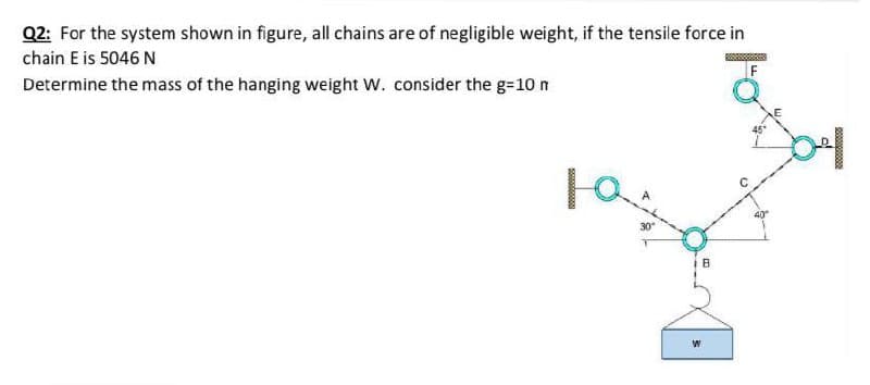
Q2: For the system shown in figure, all chains are of negligible weight, if the tensile force in chain E is 5046 N Determine the mass of the hanging weight W. consider the g=10 n


Q: 2. A uniform 80.0 N ladder 4.0 m long is placed against a frictionless wall with its base situated…
A:
Q: Q5- The gate in Figure below is 5 ft wide, is hinged at point B, and rests against a smooth wall at…
A:
Q: Q2): In figure below, assume the man only exerts a horizontal force on the box. If the coefficient…
A: Given data Weight of man = 90kg Weight of box = 140kg Coefficeint of friction of man shoe and floor…
Q: 5) In the figure shown below the person pulls the cable vertically downward to move box number 1,…
A:
Q: Q.2) Find the tension in each wire A, B and C supported a plate weighs 56 N as shown in figure. T₁=…
A: To find : The Tension in the wire A, B and C. Free body diagram : The free body diagram is,
Q: Based on the following figure and its description, answer Q1, Q2, Q3, Q4 and Q5. Isosceles…
A:
Q: consists of two rods and is loaded by the block. Given: block weight Q = 2,2 kN. Angle α = 39…
A:
Q: Q2: For the system shown in figure, all chains are of negligible weight, if the suspended block with…
A:
Q: Q4/ For the figure below the spring is used to stop a 10 kg package. If the maximum deflection in…
A: The system will continue to do work until it has exhausted its kinetic energy & potential energy…
Q: Find the tension in the cord attached to a block A. Neglect the weight of the floating pulley…
A: given; lets take tansion in cord A=Tweight of block A (wA)=400lbcoefficient of friction (f)=0.20
Q: A point of the system given below is a fixed support and point B is a moving support. Find the…
A: The free body diagram of the beam is as follows: Calculate the moment about point A is as follows:…
Q: Bar ABD in Figure P3.1 06 is supported by a hinge at B and by a cable at A. Find (a) the tension in…
A:
Q: What would be the maximum weight W of the block, shown in the following figure, so that the tension…
A:
Q: T=15 °C Given: Figure Find: Horizontal force required to hold plate in position F Q= 0.8 m3/s, PA=90…
A: This question is from fluid mechanics.
Q: Q) Consider a weight supported by a cable as shown in figure below is equal 100 kN. Determine the…
A:
Q: Suppose the pulley in the figure is suspended by a cord C (Figure Determine the tension in this cord…
A: Given data: Mass of the object on the left side, M1 = 1.2 kg. Mass of the object on the right side,…
Q: Q4/ For the figure below the spring is used to stop a 10 kg package. If the maximum deflection in…
A:
Q: Q4) A hydraulic system is shown in figure Q4. Assume the system is in equilibrium state (There is no…
A:
Q: 2. Two interconnected hydraulic cylinders are shown in Figure 2, where 1 is small cylinder piston, 2…
A: Write the given data with suitable variables.
Q: Q2) Figure 2 shows a rope that is stretched between points A and C, there is mass m at point B.…
A:
Q: Q.4 A body A weighing P, descends down an inclined plane D which makes an angle a with the…
A: Solution::
Q: Q3) A mass m = 1.96 kg lies on top of a cart. The top of the cart is an inclined plane which forms…
A: Drawing the free body diagram of the system, (a) Consider the block, Balancing forces inclined to…
Q: · Find the weight of the box in kg and the angle B for the system shown below (fig 1), consider the…
A:
Q: in the figure below weighing 99 kg/m^2, is lifted slowly by the cables AC and BC. For equilibrium,…
A:
Q: A 40 kg-mass hangs from the end of a uniform beam. The beam is 6.0 m long and has a mass of 60 kg.…
A:
Q: ka 2 ki P Rigid bar k3 for the system shown in the figure, which of the following statements are…
A: from the figure , we see that , point 1,2,3,4 are rigid on the wall , so they can't move while…
Q: Figure Q2[a] shows a shaft supported by three smooth journal bearings at A, B, and C. Given: F,-923…
A:
Q: The figure below is representative of a third class lever as in the forearm ,if the weight of…
A: Given data as per question Weight of forearm =3 kg Muscle force =4.7 N Considering the given system
Q: For figure below, the tension in the cable is 0.25 m 25° В 0.5 m 0.12 m 1.5 m 14. «N 5 m
A:
Q: C k1 k2 B b m cm a m
A: Given: The value of the mass is, m=400 kg. The value of the spring constant is, k1=5000 N/mm. The…
Q: a ladder whose length L is 12 m and whose mass is 45 kg rests against a wall. Its upper end is a…
A: Given, L = 12 m M = 45 kg h = 9.3 m m = 72 kg
Q: Q2) Figure 2 shows a rope that is stretched between points A and C, there is mass m at point B.…
A: Given data: The magnitude of mass m = 20 kg. The height h = 2 m. The length d = 3 m. The angle…
Q: 9. Two blocks of equal mass M are attached to the ends of a very light string hung over two…
A: As given that Two blocks of equal mass M at the ends there tensin will be same on each block. So the…
Q: Prob. # 3] The mass (Figure P3), m = 0.4 kg, is suspended from two springs in series with stiffness…
A:
Q: Осean Marsh d = 9 ft 5.79 A freshwater marsh is drained to the ocean through an automatic tide gate…
A: Given, b=4 ft=1.219 m, t= 3 ft= 0.914 m h= 6 ft= 1.828 m, d= 9 ft= 2.7432 m, w= 64 lb/ft3=10053.54…
Q: A uniform 80.0 N ladder 4.0 m long is placed against a frictionless wall with its base situated 2.0…
A: Given Data:- Ladder AB = 4m AC = 2m W(Ladder) = 80N To Find:- a) Force exerted by the wall ( Nw)…
Q: Shown below is a leg in a cast and supported by two cables. The combined weight of the leg and cast…
A:
Q: The block shown in the figure below is acted on by its weight, W = 1300 Lbs, a horizontal force H =…
A:
Q: Q) Consider a weight supported by a cable as shown in figure below is equal * 100 kN. Determine the…
A:
Q: 2а 4а 2а TP
A: Principle of Virtual Work: When a particle is acted upon by a set of forces in static equilibrium,…
Q: Question 2. The system shown below is composed by a flexible cable, a bar and weight with mass…
A:
Q: 1. In a room with a ceiling height of 2.6 meter, a 2.5 meter plank is supported by a cable attached…
A:
Q: A horizontal board weighing Wb = 600 N is hinged to a vertical wall. A person weighing Wp = 400 N…
A:
Q: The hydrostatic force on the gate and its position as function of h and show its direction on the…
A: Data given - d = 1 m h = 2.5 m b = 2.2 m Density of water = 1000 kg/m3 g = 9.81 m/s2 As per…
Q: What would be the maximum weight W of the block, shown in the following figure, so that the tension…
A: Ans is 401.82N
Q: Th lamp , mass = 10 Kg, is suspended in the position shown. The undeformed length of spring AB is…
A:
Q: The value of force in member CA as shown in Figure Q5 is 500 N 2 m 45 2 m 500 N A. -500 N B. 360 N…
A:
Q: -A- A man stands on the middle rung of a 250 N ladder resting on a smooth floor and against a wall…
A:
Q: Q1: Consider the traffic light (mass of 15 kg) suspend from two wires as show in the figure . find…
A:


Trending now
This is a popular solution!

Step by step
Solved in 2 steps with 2 images


- A uniform bar AB of weight W = 25 N is supported by two springs, as shown in the figure. The spring on the left has a stiffness k[= 300 N/m and natural length Lt=250 mm. The corresponding quantities for the spring on the right are k2= 400 N/m and L^ = 200 mm. The distance between the springs is L = 350 mm, and the spring on the right is suspended from a support that is a distance it = SO mm below the point of support for the spring on the left. Neglect the weight of the springs. (a) At what distance x from the left-hand spring (figure part a) should a load P = 18 N be placed in order to bring the bar to a horizontal position? (b) If P is now removed, what new value of k{is required so that the bar (figure part a) will hang in a horizontal position underweight If? (c) If P is removed and kt= 300 N/m. what distance b should spring ktbe moved to the right so that the bar (figure part a) will hang in a horizontal position under weight II"? (d) If the spring on the left is now replaced by two springs in series (kt= 300 N/m, kt) with overall natural length Lt= 250 mm (see figure part b). what value of k; is required so that the bar will hang in a horizontal position under weight IF?Solve the preceding problem for the following data: b = 8.0 in., k = 16 lb/in., a = 45°, and P = 10 lb.Solve the preceding problem for the following data: b = 6 in., b = 10 in, L = 110 ft, tan a = 1/3, and q = 325 lb/ft.
- A hollow circular pipe (see figure} support s a load P that is uniformly distributed around a cap plate at the top of the lower pipe. The inner and outer diameters of the upper and lower parts of the pipe are d1= 50 mm, d2= 60 mm, rf3 = 57 mm, and d1= 64 mm, respectively. Pipe lengths are Lt= 2 m and L, = 3 m. Neglect the self-weight of the pipes. Assume that cap plate thickness is small compared to I, and E,. Let E = 110 MPa. (a) If the tensile stress in the upper part is d = 10.5 MPa. what is load PI Also, what are reactions ft, at the upper support and R-, at the lower support? What is the stress ar(MPa) in the lower part? (b) Find displacement S(mm) at the cap plate. Plot the axial force diagram (AFD) [Ar(.f)] and axial displacement diagram (ADD)[5(.t)]. (c) Add the uniformly distributed load q along the censorial axis of pipe segment 2. Find q (kN/m) so that It, = 0. Assume that load P from part (a) is also applied.A crane boom of mass 450 leg with its center of mass at C is stabilized by two cables AQ and BQ (Ae= 304 mm2 for each cable) as shown in the figure. A load P = 20 KN is supported at point D. The crane boom lies in the y-z plane. (a) Find the tension forces in each cable: TAQand TBQ(kN}. Neglect the mass of the cables, but include the mass of the boom in addition to load P. (b) Find the average stress (s) in each cable.By what distance h does the cage shown in the figure move downward when the weight W is placed inside it? (See the figure.) Consider only the effects of the stretching of the cable, which has axial rigidity EA = 10,700 kN. The pulley at A has a diameter da= 300 mm and the pulley at B has a diameter dB= 150 mm. Also, the distance L1= 4.6 m, the distance L2=10.5 m, and the weight W = 22 kN. Note: When calculating the length of the cable. include the parts of the cable that go around the pulley sat A and B.
- A cylindrical brick chimney of height H weighs w = 825 lb/ft of height (see figure). The inner and outer diameters are d1= 3 ft and d2= 4 ft, respectively. The wind pressure against the side of the chimney is p = 10 lb/ft2 of projected area. Determine the maximum height H if there is to be no tension in the brickwork.A 150-lb rigid bar AB. with friction less rollers al each end. is held in the position shown in the figure by a continuous cable CAD. The cable is pinned at C and D and runs over a pulley at A. (a) Find reactions at supports A and B. (b) Find the force in the cable.A plane frame with a pin support at A and roller supports at C and £ has a cable attached at E. which runs over Frictionless pulleys al D and B (see figure). The cable force is known to be 400 N. There is a pin connection just Lo the left of joint C. (a) Find reactions at supports^, C, and E. (b) Find internal stress, resultants N, V, and M just to the right of joint C. (c) Find resultant force in the pin near C.
- The L-shaped arm ABCD shown in the figure lies in a vertical plane and pivots about a horizontal pin at A. The arm has a constant cross-sectional area and total weight W. A vertical spring of stiffness k supports the arm at point B. (a) Obtain a formula for the elongation of the spring due to the weight of the arm. (b) Repeat part (a) if the pin support at A is moved to D..15 A hitch-mounted bicycle rack is designed to carry up to four 30-lb bikes mounted on and strapped to two arms Gil (sec bike loads in the figure part a) The rack is attached to the vehicle at A and is assumed to be like a cant silkier beam A BCDGII (figure part b) The light of fixed segment AB is U = 10 lb. centered 9 in. from A (see figure part b) and the rest of the rack highs W2 = 40 lb. centered 19 in. from A. Segment ABCDG is a steel tube o(2 X 2 in. with a thickness I = 118 in. Segment BCDGII pivots about a bolt at B with a diameter d1 = 0.25 in. to allow access to the rear of the vehicle without removing the hitch rack. When in use, the rack is secured in an upright posit ion by a pin C(diameter o( pin d, = 5116 in.) (see phoo and figure part C). The of returning effect of the bikes on the rack is resisted by a force couple F h at BC. (a) Find the support reactions at A for the fully loaded rack. (b) Find forces in the bolt at B and the pin at C. (c) Find average shear stresses in both the bolt at Band the pin at C. (d) Find average bearing stresses o, in the bolt at B and the pin at C.In the simple cage system in the figure, which of the following is the absolute value of the force carried by the CE element in kN?