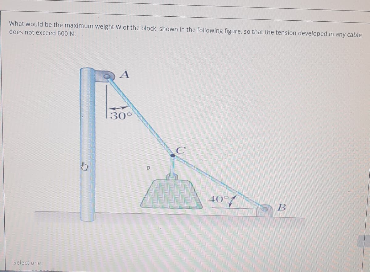
What would be the maximum weight W of the block, shown in the following figure, so that the tension developed in any cable does not exceed 600 N:
Q: What would be the maximum weight W of the block, shown in the following figure, so that the tension…
A: The free-body diagram of the provided force system is drawn below. Here, T and W represent the…
Q: Q) Consider a weight supported by a cable as shown in figure below is equal 100 kN. Determine the…
A:
Q: The load W is to be lifted using the crane shown in the figure, neglect the weight of the crane.…
A: We are authorized to answer one question at a time since you have not mentioned which question you…
Q: What would be the maximum weight W of the block, shown in the following figure, so that the tension…
A:
Q: What would be the maximum weight W of the block, shown in the following figure, so that the tension…
A:
Q: Q2: For the system shown in figure, all chains are of negligible weight, if the suspended block with…
A:
Q: ) Determine reactions in A and tension in cable as shown in figure? 300 KN 30 kN/m 20 kN/m 4m 8m T…
A:
Q: What would be the maximum weight W of the block, shown in the following figure, so that the tension…
A:
Q: A camper hangs a 32 kg pack between two trees, using two separate pieces of rope of different…
A:
Q: 6. Find the tension in each cord in Fig. 2.6 if the weight W ofthe suspended body is 150 N. 35
A: We can use Lami's theorem to solve both parts, Lami's theorem is stated as, "When three forces…
Q: What would be the maximum weight w of the block, shown in the following figure. so that the tension…
A:
Q: What would be the maximum weight W of the block, shown in the following figure, so that the tension…
A: Let the tension in string AC be T1 And the tension in string BC be T2 the angle opposite to three…
Q: 8. The knotted cords in the figure is in equilibrium. Find the tension in each cord that supports a…
A: Given Data Fw=800 N
Q: What would be the maximum weight W of the block, shown in the following figure, so that the tension…
A: Force acting in the x direction are TBCcos40=TACsin30TBC=TAC×0.65⋯⋯⋯(1) Force acting in the vertical…
Q: What would be the maximum weight W of the block, shown in the following figure, so that the tension…
A:
Q: Q.4 A body A weighing P, descends down an inclined plane D which makes an angle a with the…
A: Solution::
Q: What would be the maximum weight W of the block, shown in the following figure, so that the tension…
A: According to the given information, tension developed in a cable does not exceed 500 N. Let us…
Q: Q) Consider a weight supported by a cable as shown in figure below is equal 100 * kN. Determine the…
A:
Q: Q1/ A 30 kg mass is supported by cables as shown in figure bellow. determine tension in each cables.
A: Given: 30 kg mass To find: Tension in each cable.
Q: BI,Cf, fg Q.2) For the truss shown in figure below, determine the forces in 1o00 M 2/E
A:
Q: The block shown in the figure below is acted on by its weight, W = 1300 Lbs, a horizontal force H =…
A:
Q: A Block of weight 114 N is suspended with the help of a string. The block is pulled by a horizontal…
A:
Q: T ト ヒ
A:
Q: Assume all four objects attached to a string of length L are in equilibrium in the above figure.…
A: Draw the free-body diagram of the system. Consider joint 1, apply Lami's theorem to calculate…
Q: PROBLEM 2 For the figure shown, determine the following if the mass of the person is 50kg and the…
A: Dear student, as per the guidelines of Bartleby we are authorized to answer the first question only.…
Q: What would be the maximum weight W of the block, shown in the following figure. so that the tension…
A:
Q: What would be the maximum weight W of the block, shown in the following figure, so that the tension…
A: The free-body diagram of the joint C is drawn below. Here, T and W represent the tension and…
Q: Q2) A boom 20m long supports a load of 1200 kg as shown in the below figure. The cable BC is…
A: The given load and cable and the FBD is as shown below, T1=mgT1=12009.81T1=11.772 kN
Q: What would be the maximum weight W of the block, shown in the following figure, so that the tension…
A:
Q: calculate the forces in the ribs of the Muslim shown in Figure (1) and are the ribs of the Muslim in…
A:
Q: 2m B 3m 4m 30° 52 KN
A:
Q: Two cables are tied together at C and loaded as shown in the figure. If the weight of the load is 10…
A:
Q: What would be the maximum weight W of the block, shown in the following figure, so that the tension…
A:
Q: In the structure shown in below figure, the member which carries zero force, is a a 450 2 kN ВЕ AB O…
A:
Q: is The left support of the cable shown in Fig. located 40 ft below the right support. The cable is…
A: For the given cable, Span length, l=400 ftDifference between level of both support, d=40 ftsag of…
Q: What would be the maximum weight W of the block, shown in the following figure, so that the tension…
A:
Q: The block shown in the figure below is acted on by its weight, W = 1300 Lbs, a horizontal force H =…
A:
Q: The boom of the wall crane 4m long is held at right angles to the wall by a wire that is attached to…
A:
Q: A machine component 1.5 m long and weight 1000 N is supported by two ropes AB and CD as shown in…
A: Given Weight of the component = 1000N To find Magnitude of T1, T2
Q: 13.) Cords are loop around a small spacer separating two cylinders each weighing 400 lb and pass, as…
A: GIVEN DATA WEIGHT OF CYLINDER W=800lb WE HAVE TO FIND ANGLE AND NORMAL PRESSURE N
Q: 69. For the arrangement shown in the figure what is the force with which a person weighing 500N…
A:
Q: In the figure, L = 14 ft, P1 = 900 lb, and P2 = 550 lb. Compute the member forces listed below. In…
A: Answer: FBE = -900 lb (compression) & FBA = 2000 lb (tension)
Q: In the simple cage system in the figure, which of the following is the absolute value of the force…
A:
Q: 4.) A 20 kg block is suspended by 2 very thin ropes that meet at a 40° angle. What is the tension on…
A:
Q: P3. Two-legged ladder A man of weight W is on the top of a symmetric two-legged ladder, which is…
A: Draw the free body diagram of the ladder.
Q: The cable shown in Fig. distributed load of 25 kN per meter of horizontal length. The left support…
A: Given: uniform distributed load w=25 kN/m Height of the distance between supports, h = 50 m angle,…
Q: Cables A and B supports the 50-pound load, as shown in the figure. What is the force exerted by…
A: The free body diagram of the system is as follows:
Q: Q2: For the system shown in figure, all chains are of negligible weight, if the tensile force in…
A:
Q: What would be the maximum weight W of the block, shown in the following figure, so that the tension…
A:
Q: P Flag question What would be the maximum weight W of the block, shown in the following figure, so…
A:
Step by step
Solved in 2 steps with 2 images
- A large precast concrete panel for a warehouse is raised using two sets of cables at two lift lines, as shown in the figure part a. Cable 1 has a length L1 = 22 Ft, cable 2 has a length L2= 10 ft, and the distance along the panel between lift points Band D is d = 14 ft (see figure part b). The total weight of the panel is W = 85 kips. Assuming the cable lift Forces F at each lift line are about equal, use the simplified model of one half of the panel in figure part b to perform your analysis for the lift position shown. Find the required cross-sectional area AC of the cable if its breaking stress is 91 ksi and a factor of safety of 4 with respect to failure is desired.A crane boom of mass 450 leg with its center of mass at C is stabilized by two cables AQ and BQ (Ae= 304 mm2 for each cable) as shown in the figure. A load P = 20 KN is supported at point D. The crane boom lies in the y-z plane. (a) Find the tension forces in each cable: TAQand TBQ(kN}. Neglect the mass of the cables, but include the mass of the boom in addition to load P. (b) Find the average stress (s) in each cable.Two separate cables AC and BC support a sign structure of weight W = 1575 lb attached to a building. The sign is also supported by a pin support at O and a lateral restraint in the '-direction at D. (a) Find the tension in each cable. Neglect the mass of the cables. (b) Find the average stress in each cable if the area of each cable is Ae= 0.471 in2.
- A plane frame with a pin support at A and roller supports at C and £ has a cable attached at E. which runs over Frictionless pulleys al D and B (see figure). The cable force is known to be 400 N. There is a pin connection just Lo the left of joint C. (a) Find reactions at supports^, C, and E. (b) Find internal stress, resultants N, V, and M just to the right of joint C. (c) Find resultant force in the pin near C.An L-shaped reinforced concrete slab 12 Ft X 12 ft, with a 6 Ft X 6 ft cut-out and thickness t = 9.0 in, is lifted by three cables attached at O, B, and D, as shown in the figure. The cables are are combined at point Q, which is 7.0 Ft above the top of the slab and directly above the center of mass at C. Each cable has an effective cross-sectional area of Ae= 0.12 in2. (a) Find the tensile force Tr(i = 1, 2, 3) in each cable due to the weight W of the concrete slab (ignore weight of cables). (b) Find the average stress ov in each cable. (See Table I-1 in Appendix I for the weight density of reinforced concrete.) (c) Add cable AQ so that OQA is one continuous cable, with each segment having Force T, which is connected to cables BQ and DQ at point Q. Repeat parts (a) and (b). Hini: There are now three Forced equilibrium equations and one constrain equation, T1= T4.2.4-11 Three steel cables jointly support a load of 12 kips (see figure). The diameter of the middle cable is 3/4 in. and the diameter of each outer cable is 1/2 in. The tensions in the cables are adjusted so that each cable carries one-third of the load (ie., 4 kip). Later, the load is increased by 9 kips to a total load of 21 kips. (a) What percent of the total load is now carried by the middle cable? (b) What are the stresses crvand 0 in the middle and outer cables, respectively? Note: See Table 2-1 in Section 2.2 for properties of cables.
- A safety valve on the top of a tank containing steam under pressure p has a discharge hole of diameter d(see figure). The valve is designed to release the steam when the pressure reaches the value Pmax If the natural length of the spring, is L and its stiffness is k, what should be the dimension ft of the valve? (Express your result as a formula for h.)By what distance h does the cage shown in the figure move downward when the weight W is placed inside it? (See the figure.) Consider only the effects of the stretching of the cable, which has axial rigidity EA = 10,700 kN. The pulley at A has a diameter da= 300 mm and the pulley at B has a diameter dB= 150 mm. Also, the distance L1= 4.6 m, the distance L2=10.5 m, and the weight W = 22 kN. Note: When calculating the length of the cable. include the parts of the cable that go around the pulley sat A and B.A long re Lai nine: wall is braced by wood shores set at an angle of 30° and supported by concrete thrust blocks, as shown in the first part of the figure. The shores are evenly spaced at 3 m apart. For analysis purposes, the wall and shores are idealized as shown in the second part of the figure. Note that the base of the wall and both ends of the shores are assumed to be pinned. The pressure of the soil against the wall is assumed to be triangularly distributed, and the resultant force acting on a 3-meter length of the walls is F = 190 kN. If each shore has a 150 mm X 150 mm square cross section, what is the compressive stress
- Solve the preceding problem for W = 1.0 lb. h = 12 in.,and k =0.511,/in..15 A hitch-mounted bicycle rack is designed to carry up to four 30-lb bikes mounted on and strapped to two arms Gil (sec bike loads in the figure part a) The rack is attached to the vehicle at A and is assumed to be like a cant silkier beam A BCDGII (figure part b) The light of fixed segment AB is U = 10 lb. centered 9 in. from A (see figure part b) and the rest of the rack highs W2 = 40 lb. centered 19 in. from A. Segment ABCDG is a steel tube o(2 X 2 in. with a thickness I = 118 in. Segment BCDGII pivots about a bolt at B with a diameter d1 = 0.25 in. to allow access to the rear of the vehicle without removing the hitch rack. When in use, the rack is secured in an upright posit ion by a pin C(diameter o( pin d, = 5116 in.) (see phoo and figure part C). The of returning effect of the bikes on the rack is resisted by a force couple F h at BC. (a) Find the support reactions at A for the fully loaded rack. (b) Find forces in the bolt at B and the pin at C. (c) Find average shear stresses in both the bolt at Band the pin at C. (d) Find average bearing stresses o, in the bolt at B and the pin at C.Two steel wines support a moveable overhead camera weighing W = 28 lb (see figure part a) used For close-up to viewing of field action at sporting, events. At some instant, wire I is at an angle a = 22° to the horizontal and wire 2 is at angle fi = 40°. Wires I and 2 have diameters of 30and 35 mils, respectively. (Wire diameters are often expressed in mils; one mil equals 0.001 in.) (a) Determine the tensile stresses s and s2 in the two wires. (b) If the stresses in wires 1 and 2 must be the same, what is the required diameter of wire 1 ? (c) To stabilize the camera for windy outdoor conditions, a third wire is added (see figure part b). Assume the three wires meet at a common point coordinates (0, 0. 0) above the camera at the instant shown in figure part b. Wire I is attached to a support at coordinates (75 ft, 48 ft, 70 Ft). Wire 2 is supported at (-70 ft. 55 ft, 80 Ft). Wire 3 is supported at (-10 ft. -85 Ft, 75 ft). Assume that all three wires have a diameter of 30 mils. Find the tensile stresses in all three wires