Q2. A series of motor (Load 1) and lighting (load 2) are connected to an AC source as shown in Figure Q2. The AC source, Vs, supplies 415220° V with frequency 50 Hz. Based on this information: 5Ω 100 mH 15Q Load 1 Load 2 i) Calculate the total load impedance. Vs ii) Calculate the current, I. Figure Q2. (ii) Write the waveform expressions in frequency domain for Vs and I. Draw a phasor diagram consists of Vs and / and state the relationship between Vs and I. Determine the power factor and calculate the real power, reactive power and apparent power. Establish the power triangle for the load. (iv)
Q2. A series of motor (Load 1) and lighting (load 2) are connected to an AC source as shown in Figure Q2. The AC source, Vs, supplies 415220° V with frequency 50 Hz. Based on this information: 5Ω 100 mH 15Q Load 1 Load 2 i) Calculate the total load impedance. Vs ii) Calculate the current, I. Figure Q2. (ii) Write the waveform expressions in frequency domain for Vs and I. Draw a phasor diagram consists of Vs and / and state the relationship between Vs and I. Determine the power factor and calculate the real power, reactive power and apparent power. Establish the power triangle for the load. (iv)

Power System Analysis and Design (MindTap Course List)
6th Edition
ISBN:9781305632134
Author:J. Duncan Glover, Thomas Overbye, Mulukutla S. Sarma
Publisher:J. Duncan Glover, Thomas Overbye, Mulukutla S. Sarma
Chapter2: Fundamentals
Section: Chapter Questions
Problem 2.18P: Let a series RLC network be connected to a source voltage V, drawing a current I. (a) In terms of...

Related questions
Question
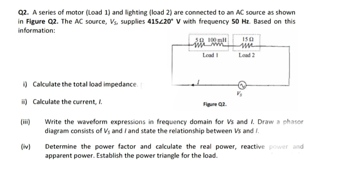
Transcribed Image Text:Q2. A series of motor (Load 1) and lighting (load 2) are connected to an AC source as shown
in Figure Q2. The AC source, Vs, supplies 415220° V with frequency 50 Hz. Based on this
information:
5Ω 100 mH
15 Q
Load 1
Load 2
i) Calculate the total load impedance.
Vs
ii) Calculate the current, I.
Figure Q2.
(ii)
Write the waveform expressions in frequency domain for Vs and I. Draw a phasor
diagram consists of Vs and I and state the relationship between Vs and I.
Determine the power factor and calculate the real power, reactive power and
apparent power. Establish the power triangle for the load.
(iv)
Expert Solution
This question has been solved!
Explore an expertly crafted, step-by-step solution for a thorough understanding of key concepts.

Step by step
Solved in 2 steps with 1 images

Knowledge Booster


Learn more about
Need a deep-dive on the concept behind this application? Look no further. Learn more about this topic, electrical-engineering and related others by exploring similar questions and additional content below.Recommended textbooks for you
Power System Analysis and Design (MindTap Course …
Electrical Engineering
ISBN:
9781305632134
Author:
J. Duncan Glover, Thomas Overbye, Mulukutla S. Sarma
Publisher:
Cengage Learning
Power System Analysis and Design (MindTap Course …
Electrical Engineering
ISBN:
9781305632134
Author:
J. Duncan Glover, Thomas Overbye, Mulukutla S. Sarma
Publisher:
Cengage Learning