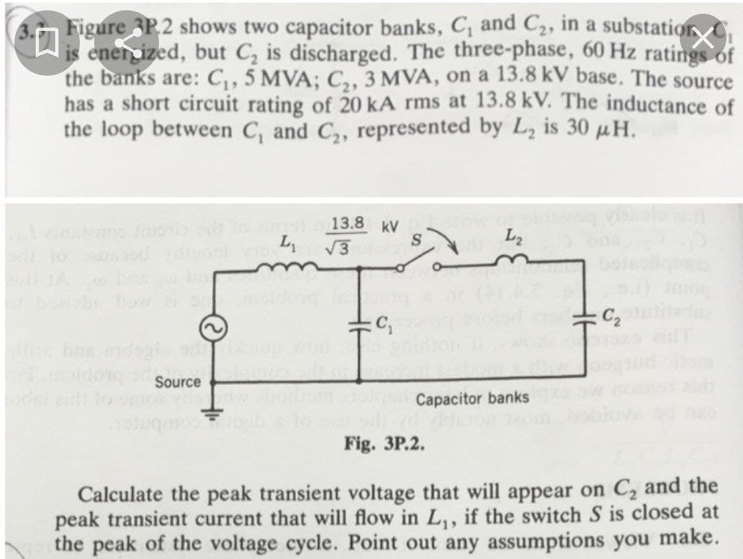
Figure 3P.2 shows two capacitor banks, C, and C2, in a substatior C is enercized, but C, is discharged. The three-phase, 60 Hz ratings of the banks are: C, 5 MVA; C,, 3 MVA, on a 13.8 kV base. The source has a short circuit rating of 20 kA rms at 13.8 kV. The inductance of the loop between C, and C,, represented by L, is 30 µH.
Figure 3P.2 shows two capacitor banks, C, and C2, in a substatior C is enercized, but C, is discharged. The three-phase, 60 Hz ratings of the banks are: C, 5 MVA; C,, 3 MVA, on a 13.8 kV base. The source has a short circuit rating of 20 kA rms at 13.8 kV. The inductance of the loop between C, and C,, represented by L, is 30 µH.

Power System Analysis and Design (MindTap Course List)
6th Edition
ISBN:9781305632134
Author:J. Duncan Glover, Thomas Overbye, Mulukutla S. Sarma
Publisher:J. Duncan Glover, Thomas Overbye, Mulukutla S. Sarma
Chapter2: Fundamentals
Section: Chapter Questions
Problem 2.18P: Let a series RLC network be connected to a source voltage V, drawing a current I. (a) In terms of...

Related questions
Question
Transcribed Image Text:3.n Figure 3P.2 shows two capacitor banks, C, and C2, in a substation C
is enercized, but C, is discharged. The three-phase, 60 Hz ratings of
the banks are: C,, 5 MVA; C,, 3 MVA, on a 13.8 kV base. The source
has a short circuit rating of 20 kA rms at 13.8 kV. The inductance of
the loop between C, and C,, represented by L, is 30 µH.
13.8 kV
V3
L
L2
o to
C2
Source
Capacitor banks
ouG OL 19
Fig. 3P.2.
Calculate the peak transient voltage that will appear on C, and the
peak transient current that will flow in L,, if the switch S is closed at
the peak of the voltage cycle. Point out any assumptions you make.
Expert Solution
This question has been solved!
Explore an expertly crafted, step-by-step solution for a thorough understanding of key concepts.

This is a popular solution!

Trending now
This is a popular solution!

Step by step
Solved in 6 steps with 3 images

Knowledge Booster


Learn more about
Need a deep-dive on the concept behind this application? Look no further. Learn more about this topic, electrical-engineering and related others by exploring similar questions and additional content below.Recommended textbooks for you
Power System Analysis and Design (MindTap Course …
Electrical Engineering
ISBN:
9781305632134
Author:
J. Duncan Glover, Thomas Overbye, Mulukutla S. Sarma
Publisher:
Cengage Learning
Power System Analysis and Design (MindTap Course …
Electrical Engineering
ISBN:
9781305632134
Author:
J. Duncan Glover, Thomas Overbye, Mulukutla S. Sarma
Publisher:
Cengage Learning