Q2. Simplify the following Boolean expression to a minimum number of literals a nd draw the logic diagrams of the circuits that implement the original and the si mplified expressions: (a) ( x' +z')(x + y' +z')
Q2. Simplify the following Boolean expression to a minimum number of literals a nd draw the logic diagrams of the circuits that implement the original and the si mplified expressions: (a) ( x' +z')(x + y' +z')

Chapter22: Sequence Control
Section: Chapter Questions
Problem 6SQ: Draw a symbol for a solid-state logic element AND.

Related questions
Question
Give solution of DLD question given below
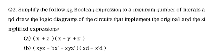
Transcribed Image Text:Q2. Simplify the following Boolean expression to a minimum number of literals a
nd draw the logic diagrams of the circuits that implement the original and the si
mplified expressions:
(a) ( x' +z' )( x + y' + z' )
(b) ( xyz + bx' + xyz' ) ( xd + x'd)
Expert Solution
This question has been solved!
Explore an expertly crafted, step-by-step solution for a thorough understanding of key concepts.

Step by step
Solved in 2 steps with 1 images

Knowledge Booster


Learn more about
Need a deep-dive on the concept behind this application? Look no further. Learn more about this topic, electrical-engineering and related others by exploring similar questions and additional content below.Recommended textbooks for you