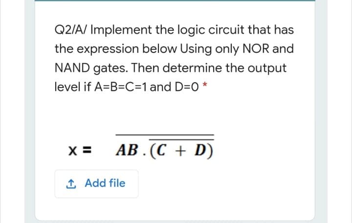
Q2/A/ Implement the logic circuit that has the expression below Using only NOR and NAND gates. Then determine the output level if A=B=C=1 and D=0 * X = АВ. (С + D)


Q: b) Implement the following Logic Circuit using C++. A, B, C, and D are the input bits while Fis the…
A: The program evaluates given input bits using logical operators and finds the value of F. The logical…
Q: A logic circuit realizes the function F(A,B,C,D) = A' B' + A' C D + A C' D+ A B' D'. Assuming that A…
A: Actually, given question regarding Boolean function:
Q: A B F From the above logic circuit, F value is o when a. All options are correct O b. A=0, B=0, C=1…
A: Answer is : All options are correct
Q: 4. Draw the logic gate circuitry for the following Boolean expressions using NOR gates only a)…
A: NOTE Below is the answer for the given question. Hope you understand it well. If you have any…
Q: Q1: Draw the circuit for this Boolean expression after simplification ,then Find the truth table…
A: The answer is in below steps:
Q: Q1: By using the Karnaugh map method, design a logic circuit with an input of 4- bit (ABCD) and one…
A:
Q: Q3/ Design a logical circuit by using the truth table below A 1 T. 1.
A:
Q: For Part B, implement a simplification of the following expression using the rules explained in…
A: We can implement these expression using basic logic gates. Logic gates AND gate…
Q: Write Boolean Function for the following Logic circuit. OM The Boolean function for above logic…
A: Connecting the output of one logic gate to the input of another logic gate is how Boolean functions…
Q: Use lucidchart.com to draw your logic circuits Write a truth table for (A + B)C Write a truth table…
A: A truth table is a logic table in which each possible input to the logic gate or boolean expression…
Q: Design a logic circuit with 3-bit inputs A, B, C that produces an output W, X, Y, Z that is equal to…
A:
Q: . Reduce the following expression, implement it using basic gates, NAND Gates only and NOR Gates t)…
A:
Q: Create a 1-bit XOR circuit using only AND, OR, and NOT gates. Explicitly show all steps starting…
A: here truth table with logical expression and circuit diagram is stated in step 2.
Q: Implement using Multiplexer 8:1 with residual variable. Please draw it using the logic gates, the…
A:
Q: Draw the logic circuit represented by the following expression: a) (A+ C)B) + (CD + Ã) + (BD) b) AB…
A:
Q: The Boolean expression for the output f of the following combinational logic circuit Q OR R R Select…
A: According to the information given:- We have to choose the correct option to satisfy the expression…
Q: Given the below Function: F(X, y, z) = (x + y). (y + z) + xyz a- Draw the combinational circuit that…
A: answer is given below:
Q: Implement the Boolean expression Y-A.B+C.B+C.A by using NAND gates and C.B.C.A) by u OR gates only.
A: Please refer to the following step for the complete solution of the problem above.
Q: Q2: A- Here's a table showing the ten and tro for each of the components in the circuit bellow.…
A:
Q: Implement a combinational circuit with three inputs x, y, and z and three outputs A, B, and C. When…
A: Combinational circuit with three inputs x, y, and z and three outputs A, B, and C are as follows:
Q: Consider the circuit as shown. If the state of (S1, SO) chänges in the sequence (0,0)-(1,1)…
A: Start by naming the AND gates A,B,C,D and OR gate as O
Q: Question: Implement the following Logic Circuit using C++ program. A, B, C, and D are the input bits…
A: Input : Given the boolean values of A, B, C, D. Output : The output value of F.
Q: Implement the following Logic Circuit using C++. A, B, C, and D are the input bits while F is the…
A: #include <iostream> using namespace std; int main() { int a,b,c,d,f; cout<<"enter…
Q: The logic circuit below is supposed to be designed to produce the truth table also shown below.…
A:
Q: Implement the following Logic Circuit using C++. A, B, C, and D are the input bits while F is the…
A: We need to solve the given Logic Circuit using the C++ programming language. Here the A, B, C, and D…
Q: raw Logic circuits for the Boolean expression Y = ( A*B)*+(C*D) , where ' * ' means complem
A: Answer:________This is a graphical representation of a logic circuit that shows the wiring and…
Q: A combinational circuit with four inputs (A, B, C, D) and one output (Z) is designed as follows…
A:
Q: Logic Circuit using C++. A, B, C, and D are th
A: Implement the following Logic Circuit using C++. A, B, C, and D are the input bits while F is the…
Q: -Y B -
A:
Q: Derive the Boolean logic expression from the following K-Map and implement the logic function using…
A: Please find the solution below in second step:-
Q: AO- For the above given logic circuit, the output Y value is =1 when the inputs of. O a. None of…
A: Here in this question we have given a circuit with output as Y. we have three input given A B C .so…
Q: Implement the following Boolean expression with exclusive- OR and AND gates: F=AB′CD′+A′BC…
A: Given boolean expression: F = AB′CD′ + A′BC D′ + AB′C′D + A′BC′D We can simplify this expression…
Q: Implement the Boolean expressions F1 and F2 given bellow with one Full Adder and any additional…
A: It is defined as a circuit can be made from standard AND and Ex-OR gates allowing us to “add”…
Q: 10 Implement the simplified expression for the following figure using NOR gates only: O X NOR YY No…
A:
Q: . Draw a circuit diagram using appropriate logic gates to implement a 3-bit comparator. Identify the…
A:
Q: Given the following truth table: Inputs ABC 000 0 001 1 010 0 011 0 100 1 101 1 110 0 111 1 e.…
A: K- map is used to simplify the boolean expression.
Q: Draw a logic circuit that would process all subtraction operation using simple addition
A: To perform the given task, let us first understand the logic behind "Subtraction by addition".To…
Q: The following circuit implements a state machine. Obtain its state table and state diagram. (You…
A:
Q: the circuit of the following state diagram has inputs SO 00 11 S3 lol 10 SI(01 10 ) S2 ID
A: The circuit of the state diagram has input
Q: Given a 4-bit signed integer, design a circuit that outputs its absolute value. You can assume that…
A: NOTE: ACCORDING TO COMPANY POLICY WE CAN SOLVE ONLY 1 PART PER QUESTION. YOU CAN RESUBMIT THE…
Q: Consider the following logic circuit. A B F a) Write the Boolean function F(A, B, C).
A: A Boolean function is a function that has n variables or entries, so it has 2n possible combinations…
Q: Implement the logic function specified in the truth table below using 4:1 multiplexer. A B CY 0 0 1…
A: Given truth table We have to implement the logic function of truth table using 4:1 multiplexer.
Q: N
A: Here in this question we have given a logic diagram with 4 input and 3 output.and we have asked to…
Q: c) Express the output column of the table below as a function of P, Q and R. Hence, design a circuit…
A: Here, we are going to draw the logic circuit for the given output. First we will find out the…
Q: Build the circuit shown here using NAND gates. Test the function of the circuit by carrying it…
A: Let the input be A and B Thus output = ((AB)') '
Q: down, starting at fifteen and ending at zero. Also, implement a reset that allows you to place it in…
A: Q. Implement a 4-bit counter that counts down, starting at fifteen and ending at zero. Also,…
Q: 3. Build a circuit using AND, OR, and NOT gates to implement the following truth table. b Output a C…
A: Designed circuit using given truth table
Q: Q1) Draw the ladder diagram for the logic circuits A&B А: A AB в AB + ĀB АВ В: S* (M+W) =…
A:

Step by step
Solved in 2 steps with 1 images


- Implement the following logic function with an 8x1 MUX. Apply the variable A, C, and Dto the selection lines. Also implement the same logic function using discrete logicgates. Compare the output waveforms.The two circuits should be created in the same schematic file using the same inputs.The two sets of outputs from the two circuits should be shown in the same waveformand simulated simultaneously.F (A, B, C, D) = (A+B+D’)(C+A)(B+D) PLEASE, JUST DRAW THE CIRCUITS OR DO IT IN QUARTUS SOFTWARE. DONOT COPY FROM CHEGG OR ANY OTHER SOURCES PLEASEUsing the truth table below ( An example sum-of-products expression is (A+B+C)(A+B+C')(A+B'+C)(A'+B+C).) a. Write a product-of-sums Boolean expression bexp4 for the output ? of the truth table b. Draw a circuit that is a direct translation of bexp4 without any simplification. For the circuit, use a layout that is analogous to the layout of the sample circuit below (where the and and or gates are appropriately swapped).Design a circuit to implement the following truth table, where A and B are inputs and Z is the output. Give the Boolean equation that implements the circuit in the space provided. There may be more than one possible correct answer. You only need to list one possible correct answer. Input Output A B Z 0 0 1 0 1 0 1 0 1 1 1 1
- implement the following circuit. Write the boolean expression describing its outputsCreate a logic circuit using only basic gates such as AND, OR, NOR, NAND, NOT, etc. to implement a Subtractor that is capable of subtracting the second number from the first, by converting the second number into its 2's complement form and then adding the resulting number to the first number. You do not need to worry about accomodating the addition or subtraction of negative numbers. Also, create a limited ALU (Arithmetic logic unit) circuit using Logism that implements a Full Adder circuit capable of adding 2 – 4 bit binary numbers and subtracting 2- 4 bit binary numbers. Also, implement the ability to select a bitwise AND operation and a bitwise OR operation. For the ALU it is acceptable to use the Adder and Subtractor circuits that are listed under the "Arithmetic" folder in Logism. (Logism tips and tricks are useful here for multi-bit pins, and how to set up different gates to support more than 1 bit. If using YOUR adder or subtractor circuit in your ALU that is not only acceptable…boolean expression: P = not((not(a.b) + c) + a.c) (c) Show that P (the Boolean expression above) is equivalent to the Boolean expression Q = a · b · not(c) and draw the corresponding circuit.
- a. Write a sum-of-products Boolean expression bexp3 for the output ? of this truth table. b. Draw a circuit that is a direct translation of bexp3 without any simplification. For the circuit, try to use the same input order and layout convention as in the example shown belowUsing the state equations and/or state table in the picture. Present a circuit. Use D Flip Flop along with any logic gate or combinatorial circuit seen in class. Clearly label all inputs and outputs.write a program to print the truth table of the following logic circuit
- Given the below Function: Draw the combinational circuit that directly implements the Boolean expression: For what values of x, y, and z the output (F) will be 0? Justify your answer using a truth table.Which of the following logic functions is implemented by the given circuit? (Hint: build a truth table of this MUX) a) f(A,B,C,D) = Σm(2,5,9,10,11,12,13,15)b) f(A,B,C,D) = Σm(0,7,8,10,11,13,14,15)c) f(A,B,C,D) = Σm(3,4,9,10,11,12,13,15)d) f(A,B,C,D) = Σm(3,5,6,7,8,12,13,15)e) f(A,B,C,D) = Σm(1,6,9,10,11,12,14,15)A. Write the Boolean equation directly from the following circuit. B. Create the truth table for the circuit above.