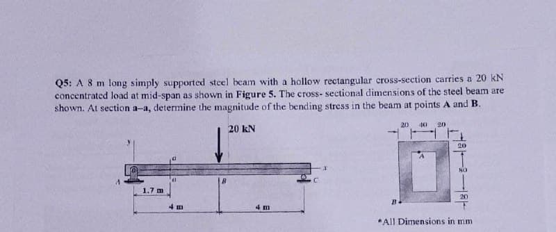
Q5: A 8 m long simply supported steel beam with a hollow rectangular cross-section carries a 20 kN concentrated load at mid-span as shown in Figure 5. The cross- sectional dimensions of the steel beam are shown. At section a-a, determine the magnitude of the bending stress in the beam at points A and B. 20 40 20 20 kN 20 1.7 m 20 4 m 4 m *All Dimensions in mm
Q: Question 5: For a rolled steel beam of an unsymmetrical I- section as shown, shown in Fig. 5. If the…
A: First calculate the position of neutral axis from bottom surface.
Q: A simply supported beam of a total length lis shown in Figure Q5, where point A supported by a pin…
A:
Q: Question # 1: Draw shear force and bending moment diagrams for the beam shown in Figure below.…
A:
Q: Figure 4 shows a simply supported timber beam AB with 4.5 m long carrying the uniformly distributed…
A:
Q: A wood beam carries the loading shown in the figure. Calculate the magnitude of the bending stress…
A:
Q: . Cantilever beam carrying a distributed load with intensity varying from Wo at the free end to zero…
A:
Q: A simply supported beam of width 100 mm, height 200 mm and length 4 m is carrying a uniformly…
A: GIVEN DATA- A SSB GIVEN WITH UDL L=4m w=10KN/m b=100mm d=200mm WE HAVE TO FIND BENDING STRESS
Q: 6.. A cantilever beam is 2.5 m long, and carries a concentrated load of 380 N at its midpoint, and…
A:
Q: A loaded, simply supported beam and its cross-section are shown in the figures below. 5 kN/m 20 mm:…
A: Solution:
Q: G4//Draw shear and bending moment diagram as shown in figure. by graphical method. 132.5KN 122.5KN.m…
A: A pin support will exert both the horizontal and vertical components of a reaction. Let the support…
Q: A simply supported beam of width 100 mm, height 200 mm and length 4 m is carrying a uniformly…
A:
Q: The rectangular section used for the simply supported beam shown in Figure Q2 is 250 mm deep and 320…
A:
Q: Example 5: Draw the shear force and bending moment diagrams for the simply supported beam as shown…
A:
Q: A simply supported beam of a total length l is shown in Figure Q5, where point A is supported by a…
A:
Q: 58 kN/m For the beam and loading shown in figure, answer the Hinge questions below -5.5 m- 254 mm 18…
A: Given data: The length of the cantilever having the uniformly distributed load is, L=5.5 m. The…
Q: A beam is partially loaded with a uniform load of 2 kN/m and a point load of 2 kN as shown below. i.…
A: RA+RB=2×3+2RA+RB=8 ......1And now taking moment about point A6×32+2×3-5RB=0RB=3KN And from equation…
Q: Situation 12: The simply supported beam in FIGURE SOM-008 is fabricated by gluing together three 160…
A: For the given simply supported beam maximum bending stress in the planks = 24 MPa To determine…
Q: The section modulus for the beam of rectangular cross section of size 80 mm x 85 mm, is…
A: Given b = 80 mm d = 85 mm
Q: A beam simply supported at the ends of a 25-ft span carries a uniformly distributed load of 1000…
A:
Q: For a beam in Figure 2, redraw the cross-section in your answer book and indicate the neutral axis…
A: The Answer is below
Q: 6. 6 The bending section modulus of a hollow cylindrical beam with an outer diameter of D and an…
A:
Q: 19. AT-section of a beam, as shown in Fig. 5.44, is subjected to a vertical shear force of 100 kN.…
A:
Q: For the beam shown in below figure 1, sketch the shear force and bending momer diagrams. And…
A:
Q: A rectangular beam of 100 mm wide is subjected to maximum shear force of 50 kN, the corresponding…
A: Given data , w= 100 mm. τmax=3 N/mm2 Vmax= 50 KN= 50000 N Let b= depth
Q: Question 1.9 A beam is constructed of a channel section. The cross section has the dimensions…
A:
Q: Figure 6 shows a beam of length 8 m, simply supported at each end, and loaded with a point load of…
A: Consider upward force & CW moment as (+)ve and downward force & CCW moment as (-)ve. Net…
Q: N for Newton, m for meter, mm for millimeter, N/(mm^2) for Stress, mm^2 or m^2 for Area, mm^4…
A: Since we only answer up to 3 sub-parts, we’ll answer the first 3. Please resubmit the question and…
Q: For the beams shown in Figure 3.5, draw the shear diagrams and note all critical values for shear.…
A: An equivalent load of uniformly distributed load refers to the single load which can be used to…
Q: 5. A mild steel shaft is subjected to a bending moment M = 400N.m and torque T = 300N.m . The…
A: Write the given data:
Q: f a total length ll is shown in Figure Q5, where point A is supported by a pin connection and point…
A: GIVEN:l1l=0.65P=mg
Q: 25 K 15 K 6ft 4 ft 3.0 K/ft 4 Use the free-body diagram pproach shown in Sections 5-3troush 5-5 o…
A: following is the answer to the above question-
Q: A simply supported beam of a total length l is shown in Figure Q5, where point A is supported by a…
A: Calculated the shear force and bending moment distributions produced in the simply support beam by…
Q: For the simply supported beam subjected to the loads shown. Let a=3.00 m, b=4.00 m, PB = 30kN, and…
A:
Q: Q/ The figure shows the vertical cross- section of a beam which at this section is subjected to a…
A: Answer: (a) The Bending stresses: ◆ Tensile stress : 1 MPa ◆ Compressive stress : 0.6 MPa (b) The…
Q: 25. A fiberglass pipe is lifted by a sling, as shown in the figure. The outer diameter of the pipe…
A: Given data as per questionLength of pipe =10 ms=4 md2=100 mmd1=100−12=88 mmweight density =1500…
Q: Span, shear force (T) and bending of the beam whose loading condition is given in Figure 4 Draw…
A: The question shows an overhanging simply supporting beam. To draw the bending moment moment diagram,…
Q: A wide flange beam as shown below is subjected to a shear force V. Using the dimensions of the cross…
A:
Q: Example (5): Draw the shear force and bending moment diagrams for the beam shown in Figure (2.13). 6…
A:
Q: Q6 The simply supported beam in Figure below has circular cross section of 60 mm as shown in Figure…
A: In the given problem, we have to find maximum bending moment to find maximum bending stress and max…
Q: 6.43-6.56 Construct the shear force and bending moment diagrams for the beam shown by the area…
A: Shear force: It is nothing but the force in transverse direction acting on a beam cross-section at…
Q: B/ Draw shear and bending moment diagram for beam loading as shown in Fig. below: 15 kN/m D. B 2 m 2…
A:
Q: A beam of size 150 mm wide, 250 mm deep carries a uniformly distributed load of w kN/m over entire…
A: For the given data and assuming it's a simply supported beam, it's configuration loading diagram…
Q: A uniformly distributed load of 226 Ib/ft is carried by a simply supported beam span. The beam is a…
A: Given data :- b =4.8 in h=5.7 in t =2.6 in
Q: 7.17 The figure shows a steel beam which is fixedly clamped in A, and which rests on a roller…
A:
Q: Draw shear force and bending moment diagrams P= 1000 N --w = 250 N/cm B 5 cm 20 cm Figure 1.2 (not…
A: Sign convention For shear force 1) RUN (right upward negative) 2) RDP ( Right Downward Positive) 3)…
Q: A simply supported beam of a total length l is shown in Figure Q5, where point A is supported by a…
A: Solution:
Q: 5kN/m 3kN/m 5m 4m 12m
A: Use point method to solve the problem (SF)A = 0 (SF)B = 5*3 =15 KN (SF)c = 15 +(5*3/2) = 22.5 KN…
Q: A horizontal beam AE, 12 m long and it carries a uniformly distributed load of 3.8 kN/m over the…
A:
Q: For the loaded beam shown in Figure Q6 below, consider section M-M and determine th following: The…
A:
Q: The figure below shows two solid homogenous rectangular beam sections with (breadth x depth)…
A:
Trending now
This is a popular solution!
Step by step
Solved in 2 steps with 2 images
- The cross section of a rectangular beam having a width b and height h is shown in part a of the figure. For reasons unknown to the beam designer, it is planned to add structural projections of width b/9 and height d/9 the top and bottom of the beam (see part b of the figure). For what values of d is the bending-moment capacity of the beam increased? For what values is it decreased?A rectangular beam with semicircular notches, as shown in part b of the figure, has dimensions h = 0,88 in. and h1 = 0.80 in. The maximum allowable bending stress in the metal beam is emax = 60 ksi, and the bending moment is M = 600 lb-in. Determine the minimum permissible width bminof the beam.A simple beam ACE is constructed with square cross sections and a double taper (see figure). The depth of the beam at the supports is dAand at the midpoint is dc= 2d 4. Each half of the beam has length L. Thus, the depth and moment of inertia / at distance x from the left-hand end are, respectively, in which IAis the moment of inertia at end A of the beam. (These equations are valid for .x between 0 and L, that is, for the left-hand half of the beam.) Obtain equations for the slope and deflection of the left-hand half of the beam due to the uniform load. From the equations in part (a), obtain formulas for the angle of rotation 94at support A and the deflection Scat the midpoint.
- Two identical, simply supported beams AB and CD are placed so that they cross each other at their midpoints (sec figure). Before the uniform load is applied, the beams just touch each other at the crossing point. Determine the maximum bending moments (mab)max* and (MCD)max beams AB and CD, respectively, due to the uniform load if the intensity of the load is q = 6.4 kN/m and the length of each beam is L = 4 m.A cantilever beam AB having rectangular cross sections with varying width bxand varying height hxis subjected to a uniform load of intensity q (sec figure). If the width varies linearly with x according to the equation hx= bBxiL^ how should the height hxvary as a function of v in order to have a fully stressed beam? (Express hxin terms of the height hBat the fixed end of the beam.)A two-axle carriage that is part of an over head traveling crane in a testing laboratory moves slowly across a simple beam AB (sec figure). The load transmitted to the beam from the front axle is 2200 lb and from the rear axle is 3800 lb. The weight of the beam itself may be disregarded. Determine the minimum required section modulus S for the beam if the allowable bending stress is 17,0 ksi, the length of the beam is 18 ft, and the wheelbase of the carriage is 5 ft. Select the most economical I-beam (S shape) from Table F-2(a), Appendix F.
- A hollow steel box beam has the rectangular cross section shown in the figure. Determine the maximum allowable shear force K that may act on the beam if the allowable shear stress is 36 MPa. cA rectangular beam with semicircular notches, as shown in part b of the figure, has dimensions h = 120 mm and h1= 100 mm. The maximum allowable bending stress in the plastic beam is emix = 6 M Pa, and the bending moment is M = 150 N · m. Determine the minimum permissible width bminof the beam.A tapered cantilever beam A B of length L has square cross sections and supports a concentrated load P at the free end (sec figure part a). The width and height of the beam vary linearly from kAat the free end to hBat the fixed end. Determine the distance.y from the free end A to the cross section of maximum bending stress if hE= 3h4, What is the magnitude ffœai of the maximum bending stress? What is the ratio of the maximum stress to the largest stress B at the support? Repeat part (a) if load P is now applied as a uniform load of intensity q = P/L over the entire beam, A is restrained by a roller support, and B is a sliding support (see figure part b).
- .2 A ligmio.irc ii supported by two vorlical beams consistins: of thin-walled, tapered circular lubes (see ligure part at. for purposes of this analysis, each beam may be represented as a cantilever AB of length L = 8.0 m subjected to a lateral load P = 2.4 kN at the free end. The tubes have a constant thickness ; = 10.0 mm and average diameters dA = 90 mm and dB = 270 mm at ends A and B, re s pec lively. Because the thickness is small compared to the diameters, the moment of inerlia at any cross section may be obtained from the formula / = jrrf3;/8 (see Case 22, Appendix E); therefore, the section modulus mav be obtained from the formula S = trdhlA. (a) At what dislance A from the free end docs the maximum bending stress occur? What is the magnitude trllul of the maximum bending stress? What is the ratio of the maximum stress to the largest stress (b) Repeat part (a) if concentrated load P is applied upward at A and downward uniform load q {-x) = 2PIL is applied over the entire beam as shown in the figure part b What is the ratio of the maximum stress to the stress at the location of maximum moment?A tapered cantilever beam A B supports a concentrated load P at the free end (see figure). The cross sections of the beam are rectangular with constant width A, depth d Aat support A, and depth ds= ^dJ2 at the support. Thus, the depth d and moment of inertia / at distance x from the free end are, respectively, in which / 4 is the moment of inertia at end A of the beam. Determine the equation of the deflection curve and the deflection S 4at the free end of the beam due to the load P.A simple beam with a W 10 x 30 wide-flange cross section supports a uniform load of intensity q = 3.0 kips/ft on a span of length L = 12 ft (sec figure). The dimensions of the cross section are q = 10.5 in., b = 5.81 in., t1= 0.510 in., and fw = 0.300 in. Calculate the maximum shear stress tjuly on cross section A—A located at distance d = 2.5 ft from the end of the beam. Calculate the shear stress rat point Bon the cross section. Point B is located at a distance a = 1.5 in. from the edge of the lower flange.