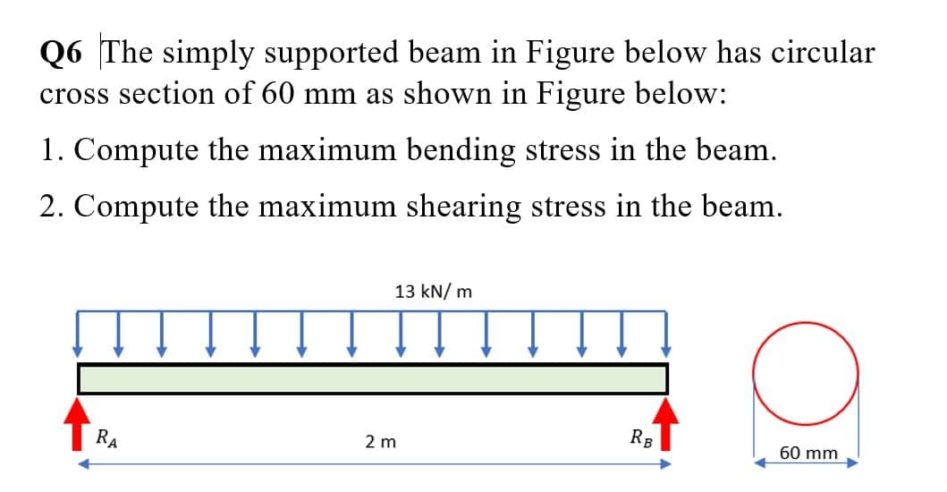
Q6 The simply supported beam in Figure below has circular cross section of 60 mm as shown in Figure below: 1. Compute the maximum bending stress in the beam. 2. Compute the maximum shearing stress in the beam. 13 kN/ m


Q: Q 1: A simply supported beam as shown in figure (1-A) below, having an I-cross section, has an over…
A:
Q: A beam ABCDE is 5 m in length and loaded as shown in Figure Q3. Draw the S.F. and B.M. diagrams for…
A: The maximum bending stress occurs at the maximum bending moment and is given by,…
Q: For the loaded beam shown in Figure Q6 below, consider section M-M and detemine the following: 6.1…
A: Given Data: Length of the beam, L=0.4+0.3+0.4=1.1 m
Q: Q : A simply supported beam shown in Figure (3-A) below, has the cross section shown in figure (3-B)…
A:
Q: A rectangular plate with notches (see figure) has dimensions h=5.75 in, h1 = 5 in and the plate…
A:
Q: A bending moment of M=150 kips-in is applied at the cross section of beam shown in Figure Question…
A:
Q: Figure 4 shows a simply supported timber beam AB with 4.5 m long carrying the uniformly distributed…
A:
Q: The figure shows a reinforced wooden beam with an aluminum channel section as seen in the figure.…
A: Given: The dimension of cross section is 6 in. by 10 in. Thickness is 0.25 in. Allowable stress in…
Q: 4.44 For the 8-in. I-beam shown in figure below, compute the maximum transverse shear stress (use…
A: First let us determine the moment of inertia of the section Moment of inertia about neutral axis =…
Q: Calculate the shear stress of the beam in the figure at point “a”?
A: Moment of inertia of an area is defined as the product of area and the distances of its center from…
Q: H.W.3 /The simply supported beam in Figure below has a rectangular cross section with dimension (30…
A:
Q: Problem 3: Computation of Shear stresses A 6m long beam with a 50 mm x 50 mm cross section is…
A:
Q: Consider the beam shown in the figure . Suppose that w1 = 560 N/m , w2 = 280 N/m . Follow the sign…
A: The detiled solution is given below.
Q: A beam is loaded as shown in the below figure. Then the bending stress along the x-x line is 5 kN 2…
A: The formula for the bending stress is. MI=σyσ=MyI Here, M is bending moment, I is moment of inertia…
Q: Q: Find the value of W which can be applied to the beam shown in figure below. if the maximum…
A:
Q: Q 2 : The cantilever beam in Figure carries a triangular load. The intensity of which varies at the…
A:
Q: The cantilever beam with variable stiffness shown in the figure is under the effect of the M…
A:
Q: 3 For the simply supported beam shown in the figure, point (C) may represent a point of…
A: Take moment about the point A, From the vertical equilibrium of forces,
Q: Example 4 The simply supported beam in Figure below has a rectangular 3kN cross section 100 mm wide…
A: Given: Uniform distributed load at the beam is, w=1.5 kN/m . Point load acting at point B is 3 kN .…
Q: For the cantilever beam with uniformly distributed load shown in Figure find: d. The moment of…
A: Consider the given cantilever beam. Calculate the reaction at the fixed end. R=16 kN/m5 mR=80 kN…
Q: Example 4 The simply supported beam in Figure below has a rectangular 3kN cross section 100 mm wide…
A: Solution: To find support reactions at A and B, considering static equilibrium,…
Q: The simple beam ACB shown in the figure is subjected to a concentrated load P 30 kips and a…
A: Given: Distributed load (q)=3kips/ftConcentrated load (P)=30kips
Q: Q.2) For a T section beam with twolong wooden planks whose dimensions (all in mm) are shown in…
A:
Q: The distributed load on the T-section beam in the figure is w = 100 kN/m. The tensile stress that…
A: Bending stress in beams When external load acts on beam shear force and bending moment are set up at…
Q: The cantilever beam is loaded as shown in the figure. Derive the equations for the shear force (V)…
A: as per Bartleby guidelines we are supposed to answer only the first three parts of the question.…
Q: Consider the beam shown in the figure. Suppose that the distributed load w = 650 lb/ft . Follow the…
A: Solution ; As the loading is symmetric, so reaction at the support will be equal :…
Q: Find the maximum transverse shear stress in the thin walled box beam shown in the figure below. This…
A:
Q: Develop the general equations for transverse shear stress in the web and flanges of the I-beam…
A:
Q: Q2: For the beam shown in figure below, find the bending stress of beam at point A. When I= 120*10*…
A: Bending equation is given as: MI=σy=ER where, M is the bending moment I is the moment of…
Q: 13 The simple beam AB shown in the figure support. concentrated load and a segment of uniform load.…
A:
Q: The simply supported beam in Figure below has a rectangular cross section 100 mm wide and 200 mm…
A:
Q: beam ABCDE is 5 m in length and loaded as shown in Figure Q3. Draw the S.F. and B.M. diagrams for…
A:
Q: H.W.1 /The cantilever beam in Figure below has a rectangular cross section with dimension (20…
A:
Q: Q: Find the value of W which can be applied to the beam shown in figure below. if the maximum…
A: Consider the reaction at the supports RB and the reaction at supports C is Rc. Moment about C,…
Q: For the cantilever beam with uniformly distributed load shown in Figure find: a. The maximum shear…
A: note: according to Bartleby guideline, we solve the first three-part of the question please repost…
Q: Box-section cantilever beam in the figure bears. Safety stresses in pressure and tension…
A: “Since you have posted a question with multiple sub-parts, we will solve first two subparts for you.…
Q: Q5: A 8 m long simply supported steel beam with a hollow rectangular cross-section carries a 20 kN…
A:
Q: Q3/ The beam shown in figure(3). carrying triangle distributed load 20KN/m and concentrated load…
A: Drawing the free body diagram of the beam as shown below, The triangular load can be written as,…
Q: simply supported beam in Figure below has a rectangular s section 120 mm wide and 200 mm high: 1.…
A:
Q: The composite beam shown in the Figure below is formed of a wood beam and a steel reinforcing plate.…
A:
Q: A rectangular section of dimensions 120 x 200 mm is used as a beam on a 3 m span. If the beam is…
A: Simply Supported beam : it is the basic structure with pinned support or roller support at the end…
Q: Draw diagram shear force and bending moment to cantilever beam which shown in the figure. W=5 KN/m…
A: The Shear Force Diagram (SFD) and Bending Moment Diagram (BMD) are very important tools to analyze a…
Q: Find the cross sectional dimensions of the smallest square beam that can be loaded as shown in the…
A: Answer: The cross-sectional dimensions of the smallest square beam: a × a = 196 mm × 196 mm
Q: A wide-flange beam (see figure) is subjected to a shear force V. h h Using the following dimensions…
A:
Q: 2. The cantilever beam shown in the figure below is subjected to loads P, = 3 kips and P, = 8.5…
A:
Q: The Cantilever beam in Fig. 5, has a circular cross section (diameter 100 mm) (a)find the shear…
A: Given data, d = Diameter of the circular cross-section = 100 mm w = Intensity of the uniform load =…
Q: Q: For the cantilever beam with uniformly distributed load shown in Figure find; a The maximum shear…
A: As per company policy, we are restricted to solve only the first three sub-part of one question at a…
Q: A simple beam with an overhang is supported at points A and B. A uniform load of w = 6 kN/m acts…
A: Given: W = 6KN/m P = 28KN L = 8m
Q: 5.10-1 through 5.10-6 A wide-flange beam (see fig- ure) is subjected to a shear force V. Using the…
A: As the question is having more than three sub parts, first three are solved.

Step by step
Solved in 3 steps with 2 images


- -1 through 5.10-6 A wide-flange beam (see figure) is subjected to a shear force V. Using the dimensions of the cross section, calculate the moment of inertia and then determine the following quantities: The maximum shear stress tinixin the web. The minimum shear stress rmin in the web. The average shear stress raver (obtained by dividing the shear force by the area of the web) and the ratio i^/t^ The shear force carried in the web and the ratio V^tV. Note: Disregard the fillets at the junctions of the web and flanges and determine all quantities, including the moment of inertia, by considering the cross section to consist of three rectangles. 5.10-4 Dimensions of cross section: b = 220 mm, f = 12 mm, h = 600 mm, hx= 570 mm, and V = 200 kN.-1 through 5.10-6 A wide-flange beam (see figure) is subjected to a shear force V. Using the dimensions of the cross section, calculate the moment of inertia and then determine the following quantities: The maximum shear stress tinixin the web. The minimum shear stress rmin in the web. The average shear stress t (obtained by dividing the shear force by the area of the web) and the ratio tmax/taver. The shear force Vweb/V carried in the web and the Vweb/V. Note: Disregard the fillets at the junctions of the web and flanges and determine all quantities, including the moment of inertia, by considering the cross section to consist of three rectangles. 5.10-1 Dimensions of cross section: b = 6 in,, ï = 0.5 in., h = 12 in,, A, = 10.5 in., and V = 30 k.-1 through 5.10-6 A wide-flange beam (see figure) is subjected to a shear force V. Using the dimensions of the cross section, calculate the moment of inertia and then determine the following quantities: The maximum shear stress tinixin the web. The minimum shear stress rmin in the web. The average shear stress raver (obtained by dividing the shear force by the area of the web) and the ratio i^/t^. The shear force i^/t^ carried in the web and the ratio V^tV. Note: Disregard the fillets at the junctions of the web and flanges and determine all quantities, including the moment of inertia, by considering the cross section to consist of three rectangles. 5.10-6 Dimensions of cross section: b = 120 mm, a = 7 mm, h = 350 mm, hx= 330 mm, and K=60kN.
- -1 through 5.10-6 A wide-flange beam (see figure) is subjected to a shear force V. Using the dimensions of the cross section, calculate the moment of inertia and then determine the following quantities: The maximum shear stress tinixin the web. The minimum shear stress rmin in the web. The average shear stress raver (obtained by dividing the shear force by the area of the web) and the ratio i^/t^ The shear force carried in the web and the ratio K b/K. Note: Disregard the fillets at the junctions of the web and flanges and determine all quantities, including the moment of inertia, by considering the cross section to consist of three rectangles. 5.10-2 Dimensions of cross section: b = 180 mm, v = 12 mm, h = 420 mm, i = 380 mm, and V = 125 kN.Draw the shear-force and bending-moment diagrams for a cantilever beam AB acted upon by two different load cases. A distributed load with linear variation and maximum intensity q0(see figure part a). A distributed load with parabolic variation and maximum intensity q0(see figure part b).A beam with a channel section is subjected to a bending moment M having its vector at an angle 8 to the 2 axis (see figure). Determine the orientation of the neutral axis and calculate the maximum tensile stress tt and maximum compressive stress crc in the beam. Use a C 200 × 20.5 channel section with M = 0.75 kN - m and 0 = 20°.
- The cross section of a rectangular beam having a width b and height h is shown in part a of the figure. For reasons unknown to the beam designer, it is planned to add structural projections of width b/9 and height d/9 the top and bottom of the beam (see part b of the figure). For what values of d is the bending-moment capacity of the beam increased? For what values is it decreased?A beam with a channel section is subjected to a bending moment M having its vector at an angle 0 to the 2 axis (see figure). Determine the orientation of the neutral axis and calculate the maximum tensile stress et and maximum compressive stress ecin the beam. Use the following data: C 8 × 11.5 section, M = 20 kip-in., tan0=l/3. See Table F-3(a) of Appendix F for the dimensions and properties of the channel section.Draw the shear-Force and bending-moment diagrams for a simple beam AB supporting two equal concentrated loads P (see figure). Repeat if the left-hand load is upward and the right-hand load is downward.
- Beam ABCD represents a reinforced-concrete foundation beam that supports a uniform load of intensity q1= 3500 lb/ft (see figure). Assume that the soil pressure on the underside of the beam is uniformly distributed with intensity q2 Find the shear force VBand bending moment MBat point B. Find the shear force Vmand bending moment M at the midpoint of the beam.A beam of length L is designed to support a uniform load of intensity q (see figure). If the supports of the beam are placed at the ends, creating a simple beam, the maximum bending moment in the beam is qL2/8. However, if the supports of the beam are moved symmetrically toward the middle of the beam (as shown), the maximum bending moment is reduced. Determine the distance a between the supports so that the maximum bending moment in the beam has the smallest possible numerical value. Draw the shear-force and bending-moment diagrams for this condition. Repeat part (a) if the uniform load is replaced with a triangularly distributed load with peak intensity q0= q at mid-span (see Fig. b).A steel beam of length L = 16 in. and cross-sectional dimensions h = 0.6 in. and h = 2 in. (see figure) supports a uniform load of intensity if = 240 lb/in., which includes the weight of the beam. Calculate the shear stresses in the beam (at the cross section of maximum shear force) at points located 1/4 in., 1/2 in., 3/4 in., and I in, from the top surface of the beam. From these calculations, plot a graph showing the distribution of shear stresses from top to bottom of the beam.