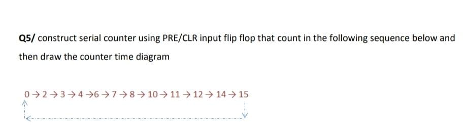
Q5/ construct serial counter using PRE/CLR input flip flop that count in the following sequence below and then draw the counter time diagram 02 3→4 6→7 8 10→ 11 12→ 14 15


Q: Write vhdl code 4-bit Universal register using d flip flop with following control mode : Parallel…
A: D flip Flop: library IEEE;use IEEE.STD_LOGIC_1164.ALL; entity d_flip_flop is Port ( D : in…
Q: Determine the Q and Q' output waveforms of the D flip-flop with D and CLK inputs are given in figure…
A: Digital circuits can either be combinational circuits or sequential circuits. Sequential circuits…
Q: Construct a synchronous 3-bit Up/Down counter with irregular sequence by using J-K flip-flops. The…
A:
Q: Considering the Figure 2 and Figure 3 draw the wave form of Q using state table of JK Flip Flop and…
A: Asynchronous inputs on a JK flip-flop have control over the outputs (Q and not-Q) regardless of…
Q: Considering the Figure 2 and Figure 3 draw the wave form of Q using state table of JK Flip Flop and…
A:
Q: a) A 4-bit ripple counter consists of flip-flops, which each have a propagation delay from clock to…
A:
Q: Q5: For the data input and clock in Figure 01 (a), determine the states of each flip-flop in the…
A: Truth table of D Flip-flop is as shown below : Clk D Q Q¯ 0 0 1 1 0 1 0 1 Q Q 0 1 Q¯ Q¯…
Q: 2- Design synchronous counter using positive edge J-K flip flop to count the following states (02…
A:
Q: Design synchronous counter(s) that go through each of the following sequence(s) f. 1 3 5 7 6 4 2 0…
A: The given sequence is: f. 1 3 5 7 6 4 2 0 and repeat
Q: Analyze the operation of the counter shown in Figure 9.114. Predict the count sequence by…
A: The Figure 9.114 is a synchronous 4-bit counter based on JK-flip flop. Write the synchronous input…
Q: Q5: Design a 2-bit synchronous counter that behaves according to the two control inputs A and B as…
A: Condition: AB: 00:No change 01 :Counts up 10: count down 11: count down Counts up:…
Q: 1. Convert SR flip-flop to JK flip-flop. 2. The following serial data have been applied to the…
A: The flipflop of one type can be realised by using another type. The output of flipflop can be…
Q: Design a Up Down Counter by using JK flip flop and verify the output of your designed circuit on any…
A: 3 bit up / down Counter, X is mode it denotes whether the counter is up/ down. X=1 =>up counter…
Q: Q4/ (Answer One Only) from the following : 1- Design synchronous counter using negative edge D- type…
A:
Q: Q: Consider the trailing edge triggered flip-flops shown: b. PRE Clock- Clock Clock CLR CLR a) Show…
A: Please find the detailed solution in below images
Q: Draw the output waveform for D flip flop the inputs shown in the timing diagram below Clock: Dinput:
A: To find the output
Q: Design a 4-bit synchronous counter that counts in 2,4,2,1 code. The counter shall count all Odd…
A: SEQUENTIAL LOGIC CIRCUITS: Sequential Logic circuits, unlike Combinational Logic circuits, have some…
Q: 2- Draw the output waveform for D flip flop the inputs shown in the timing diagram below Clock…
A: A D flip flop (DFF) has two input signals and an output signal, Q. Clock and D are the input…
Q: 2- Design Asynchronous counter using positive edge J-K flip flop to count the following states…
A: According to the desirable counter sequence, the Truth table will be Output waveform w.r.t clock…
Q: 5. A timing diagram below shows a D Flip-flop and the input clock. Show the transition of the output…
A: Writing the characteristic table of D-FF. DQnQn+1000010101111 It could be concluded from the…
Q: 2. Determine the Q waveform for the flip-flop as seen in the figure below. Assume that Q = 0…
A:
Q: Implement Logic clock divide by 2 and clock divide by 4 using minimum number of D flip flop.
A: Latch is asynchronous device. It is level triggered device. It check input and change output…
Q: Design a counter which simultaneously satisfies all of the following requirements: • Have no input •…
A: We need to design a counter circuit for the given state diagram :…
Q: 3. Construct the Finite State Machine [FSM] using JK flip flop for the following state diagram (Note…
A:
Q: Explain the distinction between synchronous and asynchronous inputs to a flip-flop.
A: Synchronous input In synchronous inputs, the signals which are input to the flip-flops are highly…
Q: 1- Design synchronous counter using negative edge D- type flip flop to count the following states:…
A:
Q: 2. Determine the Q waveform for the flip-flop as seen in the figure below. Assume that Q = 0…
A: In this question, We need to draw the output waveform of the JK filp flop. If initially Qn = 0
Q: Design a binary counter that counts from 0 to 5. At each clock pulse, 3 lights will be ON and 3…
A: Given data: A binary counter that count from o to 5. 3 light will be ON and 3 light will be OFF.…
Q: Design synchronous counter using negative edge T- type flip flop to count the following states : ( 4…
A: Given:- Count sequence Tff present state Next state T 0…
Q: The first flip-flop of a ripple counter is clocked by none of the mentioned logic 1 O the Q' of the…
A:
Q: Digital Logic Design: Design 2,4,6,8,10 Up counter using jk flip flop with timing diagram.
A: Given components: JK Flip-flops To design: Up counter that counts- 2,4,6,8,10 Timing diagram
Q: 6. Design a Modulus 5 Synchronous counter circuit by JK Flip Flop and a counting table.
A: Determine the number of flip flops needed. The type of flip flop to be used is JK flip flop.
Q: a. Complete the following timing diagram for the following circuit. The circuit works with falling…
A: a)
Q: Q4(a) Determine the Q output waveform of the flip flop in the Figure Q4(a). Assuming that the…
A:
Q: b) Using an SR latch and logic gates, design a T-N flipflop which has two input lines (T and N) and…
A: T-N Flip Flop The table is given below The Excitation Table For SR latch Qn Qn+1 S R 0 0 0 x…
Q: show the waveforms for each flip-flop output with respect For the ring counter in Figure to the…
A: Truth table of the given ring counter Clock pulse Q0 Q1 Q2 Q3 Q4 Q5 Q6 Q7 Q8 Q9 0 1 0 0 0 0 0…
Q: A) Draw a frequency divider "divide by 2" and 'divide by 4 logic circuits as a single circuit…
A: According to the question, we need to design the "Divide by 2" and "divide by 4" circuit by JK FF.…
Q: 3. Consider the counter shown in Figure 2, where the flip-flops are initially set to 0. (a)…
A: Hello. Since your question has multiple sub-parts, we will solve the first three sub-parts for you.…
Q: Design synchronous counter using negative edge D- type flip flop to count the following states : ( 4…
A:
Q: 2- Design Asynchronous counter using negative edge J-K flip flop to count the following states ( 10…
A: Here it is asked to implement an asynchronous down counter with the given counting states. Here no…
Q: Determine the system shown by state diagram in Figure 5.2 by using the positive edge triggered D…
A: The given state diagram is:
Q: a) Draw a circuit diagram for the synchronous parallel transfer of data from one three-bit register…
A: (a)Circuit for synchronous transfer data from one 3 bit register to another J-K flip flop.
Q: a. Complete the following timing diagram for the following circuit. The circuit works with falling…
A:
Q: 1- Design synchronous counter using negative edge D- type flip flop to count the following states…
A:
Q: 1) Draw a 4-bit parallel-in parallel-out register using JK Flip Flops 2) Draw a 4-bit shift right…
A:
Q: Design synchronous counter using negative edge D- type flip flop to count the following states : (4…
A: "Since you have asked multiple questions, we will solve the first question for you. If you want any…
Q: The Figure below shows a simple Moore sequence detector with an external input X. 1. Design this…
A:
Q: Draw your manually drawn synchronous counter's (utilizing D Flip-Flops) outputs' waveform te the…
A: The output waveform for the above circuit diagram can be drawn by referring to the following truth…
Q: The following serial data stream is to be generated using a J – K positive edge – triggered Flip –…
A:

Step by step
Solved in 3 steps with 6 images

- JK Flip Flop State Machine Create Logic Diagram based on Design Equations J1 = K1 = Q0 A’ , J0 = A , K0 = A’ , Y = Q0 , X = Q1 Q0’The logic diagram of JK flip-flop is given in Figure 3.a) Write the output Boolean functions for the outputs.b) Draw the timing diagram of the circuit on Figure 4. Assume that the delay between JK inputsand QQ outputs is 1 unit. Each column in Figure 4 represents 1 unit.Design a three bit synchronous binary counter that counts two by two with T-flipflops,continously. Output should be one when the counter equals maximum number.a. Draw the exitation table b. Draw the corresponding state diagram. c. Tabulate the state table for the sequential circuit. d. Draw the logic diagram of the circuit.
- You are asked to design a synchronous counter that will count the sequence 1 > 2>3>1. (a) Represent these decimal numbers in 2 bits binary numbers. (b) Write down the state table. (c) Find the functions for the next state of the state table using K-map. (d) Draw the circuit (You need to consider D flip-flops as memory unit).Q5 A Moore machine is to detect three or more consecutive zeros on an input bitstream using D flip flops. (a) Present the truth table and state diagram. (b) Interpret the simplified logic expression using K-Map. (c) Sketch the circuit with appropriate labeling.Design 2 bits counter that count down by using T flip flop when input x =1 and counts upwhen x=0. Find the following1. Derive the state table2. Derive the K‐map simplifications.3. Draw the logic diagram
- Design synchronous counters that go through each of the following sequences f. 1 3 5 7 6 4 2 0 and repeat usingi. JK flip flopsii. D flip flops Show a state diagram, indicating what happens if it initially is inone of the unused states for each of the designs.Digital Logic Design: Design 2,4,6,8,10 Up counter using jk flip flop with timing diagram.Discreet Mathematics Create the logic circuit diagram for F= XY’ + XZ
- 2- The following serial data stream is to be generated using a J – K positive edge – triggered Flip – Flop. Determine the inputs required. 101110010010111001000111.Implement a 4-bit synchronous up counter with positive edge triggered D flip flops by doing thefollowing. Up counter means counting from 0000, 0001, 0010, ... to 1111, then 0000, 0001, ....1) Derive a state table for this counter with D flip flop.2) Develop state input equations.3) Sketch a logic diagram for this counteDesign a synchronous BCD Counter based on the following conditions. If last digit of your roll number is odd then design down-counter with JK-Flip Flops by initializing the counter with last digit and count next five states. The counter should cycle back after counting five states. Hint: roll number = 169