Design a 4-bit synchronous counter that counts in 2,4,2,1 code. The counter shall count all Odd numbers in the 2,4,2,1 code. Use the minimum number of clocked JK flip flops and any necessary logic gates to build this counter. Note: treating the unused state don't care con dition s. 1. Write down the excitation table of the JK flip flop. 2 Draw the state diagram of the counter 3. Specify how many flip flop required to build this counter (explain your answer)? 4 Write down the transition table. 5 Use k-maps to find the equations of the flip flop inputs. 6. Plot the logic circuit of your counter.
Design a 4-bit synchronous counter that counts in 2,4,2,1 code. The counter shall count all Odd numbers in the 2,4,2,1 code. Use the minimum number of clocked JK flip flops and any necessary logic gates to build this counter. Note: treating the unused state don't care con dition s. 1. Write down the excitation table of the JK flip flop. 2 Draw the state diagram of the counter 3. Specify how many flip flop required to build this counter (explain your answer)? 4 Write down the transition table. 5 Use k-maps to find the equations of the flip flop inputs. 6. Plot the logic circuit of your counter.

Chapter22: Sequence Control
Section: Chapter Questions
Problem 6SQ: Draw a symbol for a solid-state logic element AND.

Related questions

Question
I need the answer as soon as possible
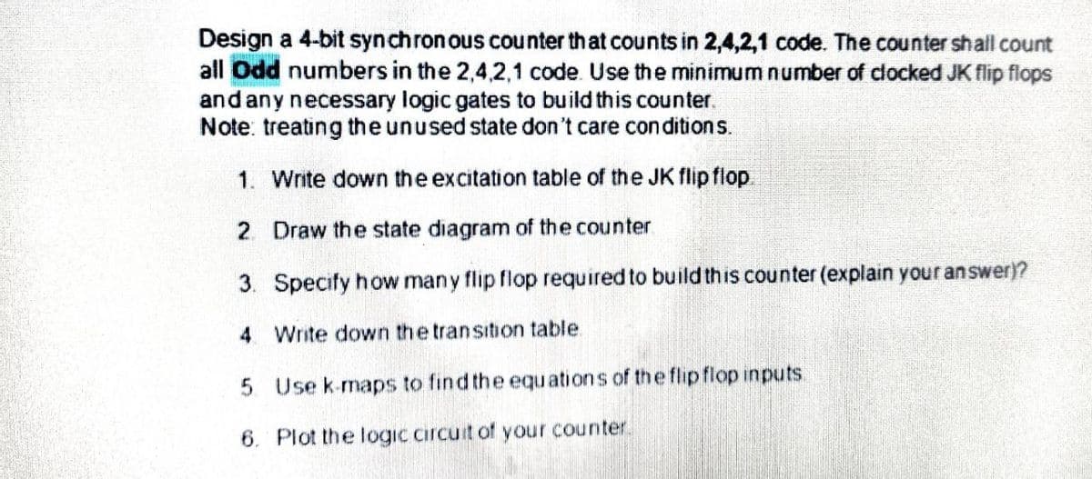
Transcribed Image Text:Design a 4-bit synchronous counter that counts in 2,4,2,1 code. The counter shall count
all Odd numbers in the 2,4,2,1 code. Use the minimum number of clocked JK flip flops
and any necessary logic gates to build this counter.
Note: treating the unused state don't care con ditions.
1. Write down the excitation table of the JK flip flop.
2. Draw the state diagram of the counter
3. Specify how many flip flop required to build this counter (explain your answer)?
4 Write down the transition table.
5 Use k-maps to find the equations of the flipflop inputs.
6. Plot the logic circuit of your counter.
Expert Solution
This question has been solved!
Explore an expertly crafted, step-by-step solution for a thorough understanding of key concepts.

This is a popular solution!

Trending now
This is a popular solution!

Step by step
Solved in 2 steps with 2 images

Knowledge Booster


Learn more about
Need a deep-dive on the concept behind this application? Look no further. Learn more about this topic, electrical-engineering and related others by exploring similar questions and additional content below.Recommended textbooks for you