QUESTION 1. Longitudinal and cross-sectional views of a beam are given in the figure below. (a) Draw the Shear Force and the Bending Moment diagrams. (b) Define the section which is critical for bending and calculate the maximum bending moment and the maximum normal stress on this section. -100 mm 9 kN/m 10 kN mm 20 mm- 80 mm 20 mm |C 60 mm -3 m 3 m
QUESTION 1. Longitudinal and cross-sectional views of a beam are given in the figure below. (a) Draw the Shear Force and the Bending Moment diagrams. (b) Define the section which is critical for bending and calculate the maximum bending moment and the maximum normal stress on this section. -100 mm 9 kN/m 10 kN mm 20 mm- 80 mm 20 mm |C 60 mm -3 m 3 m

Mechanics of Materials (MindTap Course List)
9th Edition
ISBN:9781337093347
Author:Barry J. Goodno, James M. Gere
Publisher:Barry J. Goodno, James M. Gere
Chapter3: Torsion
Section: Chapter Questions
Problem 3.11.5P: A square tube section has side dimension of 20 in. arid thickness of 0.5 in. If the section is used...

Related questions
Question
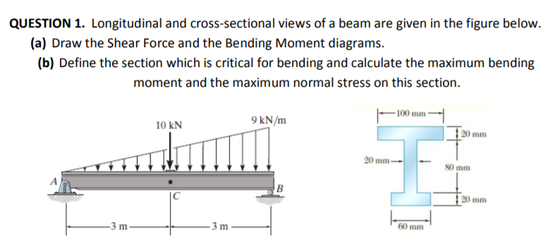
Transcribed Image Text:QUESTION 1. Longitudinal and cross-sectional views of a beam are given in the figure below.
(a) Draw the Shear Force and the Bending Moment diagrams.
(b) Define the section which is critical for bending and calculate the maximum bending
moment and the maximum normal stress on this section.
- 100 mm
9 kN/m
10 kN
20 mm
20 mm-
80 mm
20 mm
60 mm
-3 m
3 m
Expert Solution
This question has been solved!
Explore an expertly crafted, step-by-step solution for a thorough understanding of key concepts.

This is a popular solution!

Trending now
This is a popular solution!

Step by step
Solved in 2 steps with 2 images

Knowledge Booster


Learn more about
Need a deep-dive on the concept behind this application? Look no further. Learn more about this topic, mechanical-engineering and related others by exploring similar questions and additional content below.Recommended textbooks for you
Mechanics of Materials (MindTap Course List)
Mechanical Engineering
ISBN:
9781337093347
Author:
Barry J. Goodno, James M. Gere
Publisher:
Cengage Learning
Mechanics of Materials (MindTap Course List)
Mechanical Engineering
ISBN:
9781337093347
Author:
Barry J. Goodno, James M. Gere
Publisher:
Cengage Learning