Question # 2: A 2000/400 V, 100 kVA, 60 Hz step-down single-phase transformer has a primary and secondary resistances of 0.2 ohm and 0.05 ohm respectively, the corresponding leakage reactances being 0.3 ohm and 0.01 ohm respectively. Calculate the equivalent resistance, reactance and impedance referred to the low-voltage (secondary) side. 2. Find the high (primary) voltage when the transformer is supplying full-load current at rated secondary voltage at 0.8 power factor lagging. 3. 1. Draw the phasor diagram showing your answer in 2. Transformer at 0.80 pF, lag +1 V2 Load
Question # 2: A 2000/400 V, 100 kVA, 60 Hz step-down single-phase transformer has a primary and secondary resistances of 0.2 ohm and 0.05 ohm respectively, the corresponding leakage reactances being 0.3 ohm and 0.01 ohm respectively. Calculate the equivalent resistance, reactance and impedance referred to the low-voltage (secondary) side. 2. Find the high (primary) voltage when the transformer is supplying full-load current at rated secondary voltage at 0.8 power factor lagging. 3. 1. Draw the phasor diagram showing your answer in 2. Transformer at 0.80 pF, lag +1 V2 Load

Power System Analysis and Design (MindTap Course List)
6th Edition
ISBN:9781305632134
Author:J. Duncan Glover, Thomas Overbye, Mulukutla S. Sarma
Publisher:J. Duncan Glover, Thomas Overbye, Mulukutla S. Sarma
Chapter3: Power Transformers
Section: Chapter Questions
Problem 3.51P: The ratings of a three-phase three-winding transformer are Primary(1): Y connected 66kV,15MVA...

Related questions

Concept explainers
KVL and KCL
KVL stands for Kirchhoff voltage law. KVL states that the total voltage drops around the loop in any closed electric circuit is equal to the sum of total voltage drop in the same closed loop.
Sign Convention
Science and technology incorporate some ideas and techniques of their own to understand a system skilfully and easily. These techniques are called conventions. For example: Sign conventions of mirrors are used to understand the phenomenon of reflection and refraction in an easier way.
Question
2
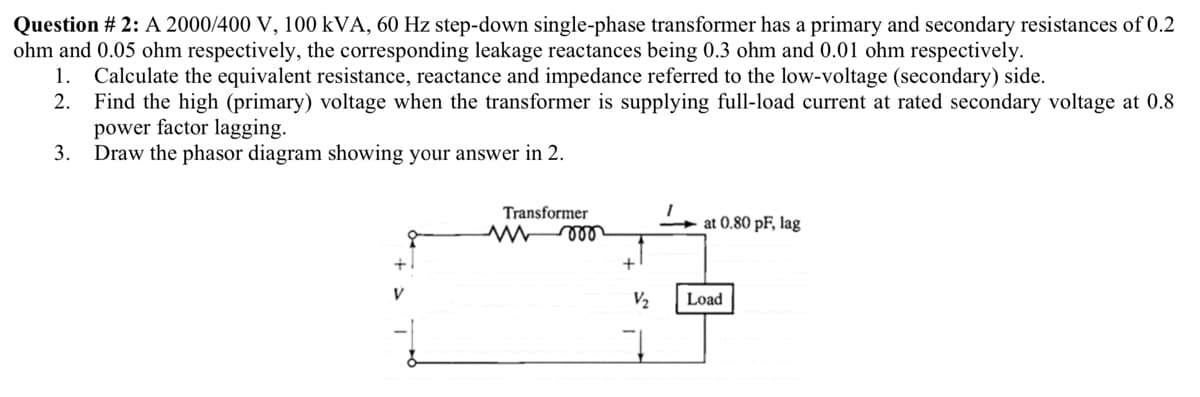
Transcribed Image Text:Question # 2: A 2000/400 V, 100 kVA, 60 Hz step-down single-phase transformer has a primary and secondary resistances of 0.2
ohm and 0.05 ohm respectively, the corresponding leakage reactances being 0.3 ohm and 0.01 ohm respectively.
Calculate the equivalent resistance, reactance and impedance referred to the low-voltage (secondary) side.
2. Find the high (primary) voltage when the transformer is supplying full-load current at rated secondary voltage at 0.8
power factor lagging.
3.
1.
Draw the phasor diagram showing your answer in 2.
Transformer
at 0.80 pF, lag
+1
V2
Load
Expert Solution
This question has been solved!
Explore an expertly crafted, step-by-step solution for a thorough understanding of key concepts.

This is a popular solution!

Trending now
This is a popular solution!

Step by step
Solved in 3 steps with 3 images

Knowledge Booster


Learn more about
Need a deep-dive on the concept behind this application? Look no further. Learn more about this topic, electrical-engineering and related others by exploring similar questions and additional content below.Recommended textbooks for you
Power System Analysis and Design (MindTap Course …
Electrical Engineering
ISBN:
9781305632134
Author:
J. Duncan Glover, Thomas Overbye, Mulukutla S. Sarma
Publisher:
Cengage Learning
Power System Analysis and Design (MindTap Course …
Electrical Engineering
ISBN:
9781305632134
Author:
J. Duncan Glover, Thomas Overbye, Mulukutla S. Sarma
Publisher:
Cengage Learning