Question 2 Design a differential amplifier like the one shown below, that has differential gain of 5 and differential input resistance of 20 ka Determine the values of R1 and R2 R2 RI Vo Vid RI R2 OR1= 20 kO and R2= 100 kn OR1= 10 kQ and R2= 50 kO OR1= 50 ko and R2= 20 k
Q: 9. If the upper critical frequency of a low frequency amplifier is 200 Hz, its bandwidth is: a) O…
A: Low frequency amplifier is also known as low pass filter means which allows frequency component…
Q: What is the value of Rf in ohms if we want a gain of -125 for an inverting amp which has an R1 =…
A:
Q: 1) Draw a shunt regulator and clearly show the four main elements. Derive an expression for the…
A:
Q: Q2 a- Draw a circuit diagram of a 311 op-amp showing an input of 10 V rms with f= 1KHZ, applied to…
A: 311 is a Differential Comparator (A s per datasheet) in which when Non Inverting voltage is…
Q: The op-amp datasheet for amplifier shown in Figure 3 has Zin-2.3 MN, Zout = 90 Q and Aol = 150,000.…
A:
Q: 4. (a). (b). Operational amplifiers (op-amps) are used in integrated circuits for signal…
A: Given a circuit of an operational amplifier as shown below. Find State characteristic of the ideal…
Q: 1.1) If the ideal OP-Amp circuit... A. are R₁-82 k and R₂= 27 k, Determine the close-loop gain. B.…
A:
Q: (c) Design the Circuit-K such that the differential gain of the operational amplifier circuit in…
A: Given: Consider the circuits shown below and note that R3 = R4, va, and vb are the input voltages,…
Q: A noninverting amplifier is built with R1 = 12 kΩ and R2 = 150 kΩ using an op amp with an open-loop…
A: Given data: Resistance R1=12 KΩ /1.2 KΩ Resistance R2=150 KΩ
Q: Problem 1. (P1) Three op-amps are connected in cascade configuration. An 80 microVolts signal is…
A: In this question , cascaded configuration of opamp is given...We have to find out gain of 3rd…
Q: 1-2-6 PÓS Check your understanding by answering these questions 1. The input stage of a 741 op-amp…
A: Op amp is an electronic circuit known as operational amplifier . It produces a single output…
Q: 2.23 Show that for the inverting amplifier if the op-amp gain is A, the input resistance is given by…
A: The derivation for Rin is as follows.
Q: 3C Problem 1. (P1) Three op-amps are connected in cascade configuration. An 80 microVolts signal is…
A:
Q: ) A differential amplifier has an output voltage given by Vo=9V1-10V2. The two inputs are V1=10mV…
A:
Q: 1. Consider the amplifier circuit shown below. Assuming that the amplifier block is an ideal op-…
A:
Q: An inverting amplifier is built with R2 =47kΩ and R1 = 2.4kΩ using an op amp with an open-loop gain…
A: Given a) Open loop-gain A=100 dB R1=2.4 kΩR2=47 kΩRid=300 kΩRod=200 kΩ convert the gain from the…
Q: Draw a shunt regulator and clearly show the four main elements. Derive an expression for the output…
A: The shunt voltage regulator where the regulating element is shunt the current to ground. The shunt…
Q: What is the value of Rf in ohms if we want a gain of -125 for an inverting amp which has an R1=4000…
A: Given : Brief description: In the above given question they want to know the designing of an…
Q: Q-2) Consider the circuit diagram given in figure 1 with R1=1KS, R2=10KQ, RF=5KN, Vi=1Volt,…
A:
Q: Assuming that the op-amps are ideal, what is the nodal voltage Vo1, Vo2, and Vout, respectively?…
A: In the Op-Amp : Voltage at inverting terminal= voltage at non inverting terminal i.e, V-=V+ […
Q: c Test 5 New Tab 3350/quizzes/31837/take Problem 1 A positive-feedback amplifier circuit (inverting…
A: Need to find V+ voltage for the given inverting schmit trigger
Q: Q.2/A Show the connection of an LM124 quad op-amp as a four-stage amplifier gains of +20, -22, -39…
A: Given data, Rf=500 kΩV1=100 μV
Q: 3B Problem 1. (P1) Three op-amps are connected in cascade configuration. An 80 microVolts signal is…
A:
Q: Q2: For the ideal op-amp shown in figure (2). Find: 1. The voltage gain A, = V₂/V₁? 2. The input…
A:
Q: V1 AV (CL) 99 O1000 il The above op-amp acts in a non ideal manner such that R2 R₁ 100 R1 0999 = 1…
A:
Q: A noninverting amplifier is designed with R1 = 1kΩ, R2 = 39 kΩ, and an op amp with an open-loop gain…
A: Converting open loop gain decibel to normal value A01=1080 dB20A01=104A01=10000 Calculating feedback…
Q: A noninverting amplifier is designed with R1 = 1kΩ, R2 = 39 kΩ, and an op amp with an open-loop gain…
A: Given R1=1 kΩR2=39 kΩA=80 dB The feedback factor for the non-inverting amplifier is given by…
Q: 3A Problem 1. (P1) Three op-amps are connected in cascade configuration. An 80 microVolts signal is…
A: Note : Please note that all the given options are incorrect by solving in simplified manner we have…
Q: (a) An operational amplifier shown in Figure 1. Sketch the real circuit model of the amplifier. As a…
A: We are answering all questions in short. It is asked to sketch the real circuit for an operational…
Q: An inverting amplifier is built with R1 =11kΩand R2 = 220 kΩ using an op amp with an open-loop gain…
A: Given : R1 =11kΩand R2 = 220 kΩ , open-loop gain of 86 dB. Closed loop gain of amplifier is…
Q: Determine the output voltage of an op-amp for input voltages of Vi1=150μV, Vi2=140μV and CMRRs of…
A: Given, Vi1 = 150 uV Vi2 = 140 uV Ad = 4000
Q: (e) industrial oven is 600 °C. A K-type thermocouple which has its characteristics shown in the…
A:
Q: Q2 R R-A VIN) O A2 VOUT VIN(+) O R R+ 4 Figure Q2 (a) (a) Figure Q2 (a) shows the circuit diagram of…
A:
Q: 5) or the circuit shown below, if the differential gain (Aa) of the op-amp is (50000) and the CMRR -…
A: In this question, if the differential gain Ad of the op-amp =50000 CMRR in (db) = 34 Find the…
Q: A Wheatstone bridge is employed to measure temperature using a sensor that will exhibit small…
A: The wheatstone bridge is shown below, We have to select an amplifier that would be best suited to…
Q: For an operational amplifier, the differential gain and the common mode gain is 5555 and 5…
A: An operational amplifier is basically a differential amplifier. This means that the differential…
Q: Question - 5 An amplifier has an unloaded voltage gain of 20, an input resistance of 10 kO (a) and…
A:
Q: Q2/B)- Show the connection of three combination op-amp stages ( Parallel and series connection)…
A: Gain of 1st stage is +110 It means op-amp in 1st stage must be non-inverting amplifier.…
Q: an operational amplifier is working as differential amplifier it takes input voltage 41 volt at…
A: Given data, Feedback resistance, Rf = 60 Ω. Input resistance, Ri = 20 Ω. Input voltage, Vi = 51 V.
Q: If feedback resistor Rf = 15k and input resistor R₁ = 5k. Then, The voltage gain of the…
A: Given data, Circuit diagram for non inverting op amp is given by, Feedback resistance, Rf=15 kΩ…
Q: In the voltage regulator circuit shown in the figure, the op-amp is ideal. The BJT has VBE=0.7 V and…
A: The given problem is from voltage regulator. The calculation is shown in the next step
Q: Select appropriate components using standard 1percent resistor values to obtain a differential…
A: As the given op-amp is ideal, it follows the virtual ground property. Using voltage division rule,…
Q: 68ΚΩ +12V + Vo 22kΩ Va -9V 72k92 a. Calculate vo when VG = 3V. b. Specify the range of values of v…
A: Operational amplifier: The operation amplifier is used to amplify the signal and it is three…
Q: Q2 A non-inverting amplifier shown in Figure 3. The input Vs of the amplifier will be over the…
A: Part (i): For the ideal op-amp, the voltage at the non-inverting terminal is equal to the voltage at…
Q: For an input of V1 = 100 mV in an inverting amplifier whose closed-loop voltage gain is 40,…
A:
Q: An opamp is working as both inverting and non inverting amplifier then examine it's performance by…
A: Performance of OP amp is obtained considering different parameters such as input voltage, input…
Q: Find the slew rate of op-amp from the output waveform given below? Given: V1=12.8 V, V2= -9.8 V and…
A: Slew rate is defined as the change in voltage or current per unit time. Slew Rate = ΔVt=V1-V2t Here…
Q: If feedback resistor R₁ = 10k and input resistor R₁ = 2k. Then, The voltage gain of the inverting…
A:
Q: The inverting amplifier in the circuit shown has an input resistance of 400 k0, an output resistance…
A:
correct and clear or dislike
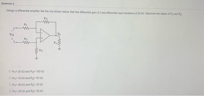
Trending now
This is a popular solution!
Step by step
Solved in 2 steps with 2 images
- An inverting amplifier is built with R2 =47kΩ and R1 = 2.4kΩ using an op amp with an open-loop gain of 100 dB, an input resistance of 300 kΩ, and an output resistance of 200 Ω. What are the closed-loop gain, input resistance, and output resistance for this amplifier? (b) Repeat if the open-loop gain is changed to 94 dB.Q2/B)- Show the connection of three combination op-amp stages ( Parallel and series connection) using an LM348 IC to provide outputs that are 110, 400, and 2601 times larger than the input. Use a feedback resistor of Rf = 500 k? in all stages, while can use only (R= 50 k? for first stage), (R= 25 k? for second stage), and (R= 10 k? for third stageQuestion 1: a. For the circuit shown, determine V0 when R1 = 1.8 kΩkΩ, R2 = 80 kΩ, Vx = 100 mV, Vy = 10 mV, and Vcc = 15V. b. For the circuit shown, determine R1 such that V0=m×(Vx−Vy). Assume mmm = 5.0 and R2 = 50 kΩ and that the op-amp is in its linear region of operation.
- A noninverting amplifier is built with R2 = 75 kΩ and R1 = 5.6kΩ using an op amp with an open -loop gain of 100dB, an input resistance of 500kΩ, and an output resistance of 300 Ω. What are the closed-loop gain, input resistance, and output resistance for this amplifier? (b) Repeat if the open-loop gain is changed to 94 dB.A noninverting amplifier is built with R1 = 12 kΩ and R2 = 150 kΩ using an op amp with an open-loop gain of 86 dB. What are the closed-loop gain, the gain error, and the fractional gain error for this amplifier? (b) Repeat if R1 is changed to 1.2 kΩ.An inverting amplifier is built with R1 =11kΩand R2 = 220 kΩ using an op amp with an open-loop gain of 86 dB. What are the closed-loop gain, the gain error, and fractional gain error for this amplifier? (b) Repeat if R1 is changed to 1.1 kΩ.
- A noninverting amplifier is built with R2 = 47 kΩ and R1 = 6.2k Ω using an op amp with an open-loop gain of 94 dB. What are the closed-loop gain, the gain error, and the fractional gain error for this amplifier? (b) Repeat if the open-loop gain is changed to 100 dB.Show the connection of a three-stage amplifier with gains of +10, -18, and -27.Use a 270-kΩ feedback resistor for all three 741 op-amp circuits. What outputvoltage will result for an input of 150 mV?Design an amplifier with an overall gain Av = -15 where the input voltage vi has a source impedance (Ri) of 2kW and the amplifier has an input impedance of 4kW, VBE,on = 0.7V and β =200. The amplifier requires a maximum output voltage swing. Determine all resistor values, Ai and the maximum voltage swing.
- The amplifier as shown has R1 = 8.2 k ,R2 = 160 k and operates from ±12-V powersupplies. (a) What is the voltage gain Av = vo/viof the circuit? (b) Suppose input source vi is notideal but actually has a 1.5 k source resistance.What is the voltage gain Av = vo/vi?It is understood that the voltage comparators can utilise either a no-feedback (open-loop) operation or a positive-feedback operation. The op-amp LF411 is a high-speed comparator and for a circuit utilising it (shown in Fig. A2c), assume that an input (Vin) with 10 V peak amplitude at 1 Hz frequency is being applied. Please describe and draw the comparator output (Vo) by clearly labelling axes, threshold voltages and the saturation voltages in your sketch. Also show any supporting calculations including the calculation of Vref at the non-inverting terminal.Q4/A)- Show the connection of three combination op-amp stages using an LM348 IC to provide outputs that are 110, 1681, and 420 times larger than the input. Use a feedback resistor of Rf = 400 k? in all stages, while can use only (R= 40 k? for first stage), (R= 10 k? for second stage), and (R= 20 k? for third stage