Question 2: The cross-sectional area for the lattice rods in the figure is A=120 mm2, the modulus of ela if the singular loads shown in the figure are affected, how many mm is the length of the BC rod under the influence 120 kN
Question 2: The cross-sectional area for the lattice rods in the figure is A=120 mm2, the modulus of ela if the singular loads shown in the figure are affected, how many mm is the length of the BC rod under the influence 120 kN

Mechanics of Materials (MindTap Course List)
9th Edition
ISBN:9781337093347
Author:Barry J. Goodno, James M. Gere
Publisher:Barry J. Goodno, James M. Gere
Chapter2: Axially Loaded Members
Section: Chapter Questions
Problem 2.11.4P: A prismatic bar in tension has a length L = 2.0 m and cross-sectional area A =249 mn2. The material...

Related questions
Question
5
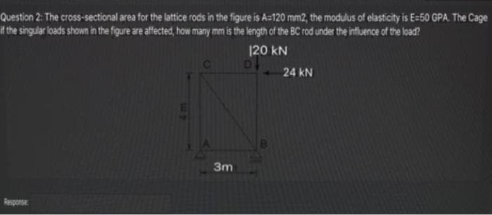
Transcribed Image Text:Question 2: The cross-sectional area for the lattice rods in the figure is A=120 mm2, the modulus of elasticity is E=50 GPA. The Cage
it the singular loads shown in the figure are affected, how many mm is the length of the BC rod under the influence of the load?
120 kN
24 kN
3m
Response
Expert Solution
This question has been solved!
Explore an expertly crafted, step-by-step solution for a thorough understanding of key concepts.

Step by step
Solved in 3 steps with 3 images

Knowledge Booster


Learn more about
Need a deep-dive on the concept behind this application? Look no further. Learn more about this topic, mechanical-engineering and related others by exploring similar questions and additional content below.Recommended textbooks for you
Mechanics of Materials (MindTap Course List)
Mechanical Engineering
ISBN:
9781337093347
Author:
Barry J. Goodno, James M. Gere
Publisher:
Cengage Learning
Mechanics of Materials (MindTap Course List)
Mechanical Engineering
ISBN:
9781337093347
Author:
Barry J. Goodno, James M. Gere
Publisher:
Cengage Learning